
The Sellita SW200-1 is an 11½-ligne Swiss automatic mechanical movement widely used in independent, microbrand, and established production watches.
For watch case design, the SW200-1 should not be treated as a simple circular object with a diameter and height. It is a fixed internal mechanical system with casing geometry, stem-axis requirements, dial-side relationships, rotor clearance requirements, hand-height options, clamp arrangements, and service-access needs.
The headline dimensions identify the movement.
They do not define the finished watch case.
A professional SW200-1 case must resolve four linked engineering groups:
- movement location and retention
- radial clearance, axial stack, and rotor protection
- stem-axis, crown-tube, dial, date, and hand-height relationships
- sealing, tolerances, assembly, inspection, and service access
HorologyCAD treats the SW200-1 as a benchmark movement for movement-led watch case design because it demonstrates the difference between reading a manufacturer specification and converting that information into a manufacturable, serviceable, and tolerance-aware case architecture.
This page separates two information layers:
Official Sellita Manufacturer Data
Specifications, dimensions, drawings, and movement relationships defined by Sellita documentation.
HorologyCAD Engineering Interpretation
Case-design guidance explaining how those manufacturer references affect movement location, clearance, retention, assembly, sealing, serviceability, and manufacturability.
Manufacturer documentation defines the movement.
HorologyCAD explains what that movement requires from the case.
| Specification | Manufacturer reference |
|---|---|
| Calibre | Sellita SW200-1 |
| Movement type | Swiss automatic mechanical |
| Ligne size | 11½ lignes |
| Overall movement diameter | 26.00 mm |
| Case-fitting diameter | 25.60 mm |
| Movement height | 4.60 mm |
| Frequency | 28,800 A/h / 4 Hz |
| Jewels | 26 |
| Running time | Minimum 38 hours; typical 41 hours |
| Winding | Automatic and manual |
| Stop seconds | Yes |
| Display | Central hours, minutes, and seconds; date window with quick correction in the documented execution |
| Oscillating weight | Heavy-metal segment with ball-bearing support |
| Balance lift angle | 50° |
| Total setting-stem travel | 0.80 mm |
| Standard hand-fitting execution | Height 2 |
| Case-design status | Execution dependent |
SW200-1 Quick Reference
Ligne Size Note
The ligne is a traditional Swiss and French watchmaking unit used to classify movement size. One ligne equals 2.2558 mm, although ligne classifications are nominal and should not be treated as controlling engineering dimensions.
For watch-case design and CAD development, use the movement’s official metric dimensions rather than the ligne classification.
SW200-1 Quick Reference Card

Key Design Note
The 26.00 mm overall movement diameter and 25.60 mm case-fitting diameter describe different physical relationships.
The 26.00 mm dimension identifies the broader physical movement envelope.
The 25.60 mm dimension identifies the principal manufacturer-defined casing-fit reference.
Neither dimension automatically defines the finished case cavity.
The 4.60 mm movement height also does not define the total finished watch thickness.
Final case geometry must additionally account for:
- locating surfaces
- holder or casing-ring geometry
- assembly clearance
- anti-rotation control
- casing clamps
- dial support
- selected hand height
- rotor clearance
- caseback construction
- crown and stem alignment
- gasket systems
- manufacturing variation
- service access
A movement dimension becomes useful only when its function within the complete watch system is understood.
Official Manufacturer Source
| Item | Reference |
|---|---|
| Manufacturer | Sellita Watch Co. SA |
| Calibre | SW200-1 |
| Primary document | Sellita SW200-1 Technical Documentation |
| Document revision | 07 |
| Document date | 2 September 2024 |
| HorologyCAD archive reference | HC-MTS-SW200-1-REV07 |
The official Sellita technical document is the primary source for manufacturer-defined information on this page.
It contains information relating to:
- movement specifications
- movement grades and timing criteria
- winding and testing
- component identification
- movement assembly
- automatic winding assembly
- setting-stem removal
- theoretical inner movement position
- casing frame
- casing fits
- casing-clamp options
- dial indications
- date geometry
- hand-fitting heights
- hand-fitting heights without central seconds
- setting-stem length
- crown position
- screw-down crown relationships
Where information is described as official manufacturer data, it should be traceable to the relevant Sellita document section.
The technical document does not remove the need to inspect the exact movement and components used in the project.
Manufacturer-Document Use
The original Sellita technical documentation should be linked for attribution and verification.
The manufacturer drawings contain protected technical material. HorologyCAD should therefore not reproduce complete Sellita drawings without the appropriate permission.
HorologyCAD technical visuals and explanations should be:
- independently created
- clearly source-attributed
- based on verified manufacturer references
- explanatory rather than copied
- labelled according to source status
This maintains a clear distinction between:
- Sellita documentation
- HorologyCAD engineering interpretation
- HorologyCAD original explanatory material
Readers should consult the original manufacturer document for the complete Sellita specification.
Verification and Revision Notes
| Item | Status |
|---|---|
| Manufacturer | Sellita Watch Co. SA |
| Calibre | SW200-1 |
| Primary source | Sellita SW200-1 Technical Documentation |
| Document revision | 07 |
| Document date | 2 September 2024 |
| Initial HorologyCAD source review | 17 June 2026 |
| Manufacturer documentation audit | Completed |
| Physical movement validation | Pending |
| Prototype validation | Pending |
| Page status | Manufacturer-documentation audited flagship draft |
Verification Scope
The manufacturer specifications and principal case-integration relationships used on this page have been checked against the identified Sellita technical documentation.
The audit covers:
- headline specifications
- overall and case-fitting diameters
- movement height
- casing-frame geometry
- casing options
- casing clamps
- dial interface
- date-window geometry
- hand-fitting-height system
- stem length
- setting-stem travel
- crown position
- crown-impact guidance
- screw-down crown operating positions
- movement grades
- timing criteria
- winding-test information
- setting-stem removal
HorologyCAD guidance concerning finished cavity sizing, holder strategy, radial clearance, axial clearance, anti-rotation, caseback architecture, sealing, tolerances, assembly, inspection, and prototype acceptance is engineering interpretation.
It is not a universal set of Sellita-prescribed case dimensions.
Configuration Warning
Final case geometry must be checked against:
- physical calibre marking
- exact movement execution
- current technical document
- date configuration
- selected hand-fitting height
- dial construction
- setting-stem option
- casing-clamp or holder arrangement
- crown and tube system
- actual movement sample where practical
Nominal similarity to the ETA 2824-2 or another Sellita-family movement does not prove complete casing interchangeability.
SW200-1 Compared With Other Common Watch Movements
The SW200-1 is one of several common automatic movements used in modern watch case design. Comparing it with alternatives such as the ETA 2824-2, Sellita SW300-1, Miyota 9015, and Seiko NH35 helps show why movement diameter, height, stem position, rotor clearance, and caseback architecture must be considered before the external case shape is finalised.

Technical Source Classification
The following hierarchy applies throughout this page.
Level A — Direct Manufacturer Specification
A value stated explicitly in official Sellita documentation.
Level B — Manufacturer Drawing Interpretation
A dimension or relationship read directly from an official Sellita technical drawing.
Level C — Execution-Dependent Manufacturer Information
A value or relationship that may change according to movement execution, date arrangement, dial configuration, hand-fitting height, supplied stem, or casing components.
Level D — HorologyCAD Engineering Interpretation
Case-design guidance developed from manufacturer information and movement-led engineering principles.
Level E — Project-Specific Validation
A relationship requiring confirmation through selected components, physical measurements, tolerance analysis, prototype assembly, functional testing, or production inspection.
Level D and Level E information must not be represented as official Sellita specifications.
Manufacturer Source Register
| Subject | Sellita document page |
|---|---|
| Technical specifications | Page 3 |
| Winding, running time, and movement grades | Page 4 |
| Timing and performance criteria | Page 5 |
| Component list | Pages 6–7 |
| Movement assembly | Pages 8–17 |
| Setting-stem removal | Page 18 |
| Frame for case | Page 19 |
| Casing options and clamps | Page 20 |
| Dial indications | Pages 21–22 |
| Hand-fitting heights | Page 23 |
| Hand-fitting heights without central seconds | Page 24 |
| Setting-stem length and crown position | Page 25 |
| Screw-down crown positions | Page 26 |
The visible Sellita document page numbers should be used when referring readers to the manufacturer PDF.
Manufacturer Data Register
| Data item | Manufacturer reference | Source class |
|---|---|---|
| Calibre | SW200-1 | Level A |
| Overall movement diameter | 26.00 mm | Level A / B |
| Case-fitting diameter | 25.60 mm | Level A / B |
| Movement height | 4.60 mm | Level A |
| Frequency | 28,800 A/h / 4 Hz | Level A |
| Jewel count | 26 | Level A |
| Running time | Minimum 38 hours; typical 41 hours | Level A |
| Balance lift angle | 50° | Level A |
| Total setting-stem travel | 0.80 mm | Level B |
| Casing fits | Multiple manufacturer-defined options | Level B / C |
| Casing clamps | Multiple options | Level B / C |
| Dial geometry | Execution dependent | Level B / C |
| Revised date-window dimension | 2.30 mm | Level B / C |
| Revised date-window centre distance | 10.40 mm | Level B / C |
| Hand-fitting heights | Eight three-hand arrangements | Level B / C |
| Standard hand-fitting execution | Height 2 | Level B / C |
| Hand heights without central seconds | Separate manufacturer table | Level B / C |
| Normal setting-stem option | Manufacturer-defined | Level B / C |
| Long setting-stem option | Manufacturer-defined | Level B / C |
| Setting-stem thread | S0.90 | Level B |
| Crown-to-middle maximum gap | 0.10 mm | Level A / B |
| Movement grades | Elaboré, Top, and Chronomètre | Level A |
| Stem-removal tool | 1.00 mm screwdriver | Level A |
| Stem-removal position | Time-setting position | Level A |
Every numerical value used in released production CAD should be checked against:
- applicable drawing page
- document revision
- exact movement execution
- drawing convention
- stated tolerance
Where a drawing is unclear, an inference should not be presented as confirmed manufacturer data.
Record Before Beginning CAD
Before developing the case, create a project-specific movement record.
Record:
- manufacturer
- calibre
- physical movement marking
- movement grade
- supplier
- purchase date
- date execution
- hand-fitting-height code
- dial specification
- dial thickness
- dial attachment
- intended hand set
- setting-stem option and reference
- selected casing clamp
- clamp bend and length
- clamp screw type
- movement-holder strategy
- crown type
- crown-tube architecture
- manufacturer-document revision
- physical measurements
- known component deviations
- CAD revision
- prototype revision
A movement should not be represented only by a vague project label such as “SW200 case.”
The project record should identify the exact movement and component configuration around which the case is being developed.
Why the SW200-1 Matters
The SW200-1 occupies an important position in practical Swiss automatic watchmaking.
Its value does not come from rarity.
It comes from being:
- established in production
- familiar to watchmakers
- serviceable
- commercially realistic
- suitable for independent brands
- supported by an established supplier and service ecosystem
- recognised by collectors
These qualities reduce movement-selection risk.
They do not remove case-design risk.
A familiar movement can still be integrated badly.
Poor SW200-1 integration can produce:
- rough winding
- poor setting feel
- crown and stem misalignment
- rotor contact
- weak movement retention
- date-window misalignment
- dial displacement
- insufficient hand clearance
- excessive watch thickness
- sealing problems
- difficult servicing
A correctly integrated SW200-1 can produce a watch that feels robust, controlled, and professionally resolved.
The difference lies in the surrounding architecture.
Sellita and the SW200 Family
The SW200 family belongs to the established 11½-ligne Swiss automatic movement category used across practical three-hand watches.
Sellita is a Swiss movement manufacturer based in La Chaux-de-Fonds, an important centre of Swiss watchmaking. The company became especially important to the wider watch industry as independent and non-integrated brands sought reliable Swiss mechanical movements outside fully in-house production. Within that context, the SW200 family became one of the most widely used practical Swiss automatic movement families for brands requiring a familiar, serviceable and well-documented calibre.
The SW200-1 became particularly relevant to independent and non-integrated brands requiring a recognised and serviceable Swiss automatic movement without developing a proprietary calibre.
Current Calibre Status
This page covers the Sellita SW200-1.
Sellita has since introduced the SW200-2 as an evolution of the SW200 family.
An SW200-1 project must be validated against SW200-1 documentation.
An SW200-2 project must be validated separately against the technical information applicable to the SW200-2.
The SW200-1 remains important because it continues to appear in:
- existing production watches
- service and repair work
- legacy designs
- replacement-case projects
- established dial and hand programmes
- independent-brand products
- microbrand watches
The purpose of this page is not to present the SW200-1 as Sellita’s latest movement development.
It is to provide a rigorous engineering reference for projects that actually use the SW200-1.
Movement Architecture
The documented SW200-1 execution provides:
- central hours
- central minutes
- central seconds
- date through a window
- quick date correction
- automatic winding
- manual winding
- stop seconds
- central oscillating weight with a heavy-metal segment
- ball-bearing rotor support
- conventional dial-side hand and calendar architecture
The architecture is familiar.
It is not mechanically trivial.
The case designer must coordinate:
- overall movement envelope
- casing-fit diameter
- stepped movement geometry
- locating surfaces
- holder or casing ring
- casing clamps
- dial attachment
- date display
- selected hand stack
- setting stem
- keyless works
- crown tube
- crown
- rotor envelope
- caseback
- rehaut
- crystal
- gaskets
The SW200-1 is not an ultra-thin movement.
Its movement height and automatic winding system must be considered before the external case profile is fixed.
SW200-1 Movement Architecture Diagram

Movement Grades and Timing Performance
Sellita identifies several SW200-1 movement grades, including:
- Elaboré
- Top
- Chronomètre
Movement grade should not be confused with movement variant.
A grade principally concerns:
- regulation
- positional performance
- quality-control limits
- component selection
- finishing
- commercial positioning
A movement variant or execution may affect physical case integration through:
- calendar arrangement
- hand-fitting height
- display system
- dial geometry
- supplied casing components
Manufacturer timing criteria are useful for:
- movement specification
- procurement
- quality control
- regulation expectations
- final product positioning
They do not change the basic 26.00 mm overall envelope, 25.60 mm case-fitting diameter, or 4.60 mm movement height.
The exact grade should nevertheless be recorded in the project movement register.
Appropriate Applications and Limitations
The SW200-1 offers a practical balance of:
- Swiss manufacture
- serviceability
- supplier availability
- production familiarity
- collector recognition
- established technical documentation
- suitability for modest production volumes
It is particularly appropriate for:
- dive watches
- field watches
- pilot watches
- tool watches
- sports watches
- robust dress watches
- independent-brand production
- serviceable long-term watches
It is less naturally suited to projects centred on:
- extreme thinness
- unusually long power reserve
- unconventional display architecture
- movement decoration as the main visual attraction
These are application boundaries rather than defects.
The movement should be selected because it suits the intended watch architecture.
Movement origin cannot compensate for weak case integration.
From Manufacturer Data to Case Architecture
Manufacturer documentation tells the designer what the movement is.
It does not completely determine how the watch case should be built.
The case designer must still establish:
- locating datums
- cavity strategy
- holder geometry
- casing-clamp use
- radial clearance
- anti-rotation
- axial retention
- stem-axis transfer
- crown-tube geometry
- rotor protection
- caseback depth
- dial support
- hand clearance
- sealing
- tolerances
- assembly
- inspection
- service removal
The central HorologyCAD principle is:
A movement dimension becomes useful only when its role within the complete watch system is understood.
SW200-1 Casing Envelope
Sellita’s casing-frame drawing defines the SW200-1 as a stepped three-dimensional movement envelope.
It distinguishes between:
- 26.00 mm overall movement diameter
- 25.60 mm principal case-fitting diameter
- smaller stepped movement-body regions
- dial-side and caseback-side axial references
- movement support relationship
- setting-stem centreline
- total setting-stem travel
These dimensions serve different functions.
The 26.00 mm dimension describes the broader physical movement envelope.
The 25.60 mm dimension identifies the principal manufacturer casing-fit reference.
The smaller stepped diameters describe additional body and support geometry that may affect:
- movement-holder design
- internal cavity relief
- clamp access
- movement insertion
- service removal
- component clearance
The finished case cavity should therefore not be represented as one unsupported cylindrical diameter.
The designer must determine:
- which feature locates the movement
- which regions require clearance
- which surface establishes the support plane
- how the holder or clamps interact with the case
- how the complete movement enters and leaves the case
Sellita also instructs that the distance to the movement centre should be checked before casing a production series.
This supports an important HorologyCAD principle:
Nominal source geometry establishes the design basis, but production release still requires project-specific verification.
Related engineering reference: Internal Case Geometry & Movement Cavity Sizing
SW200-1 Internal Case Envelope Diagram

Movement Diameter and Internal Case Geometry
The 25.60 mm case-fitting dimension establishes a manufacturer casing reference.
It does not automatically establish the finished case-cavity diameter.
The internal case may also need to accommodate:
- a movement holder
- casing ring
- locating shoulders
- casing clamps
- clamp screws
- radial assembly clearance
- coating or finishing buildup
- anti-rotation features
- inspection access
- service-tool access
A cavity modelled directly at the nominal movement dimension may become difficult or impossible to assemble after manufacturing variation is introduced.
It may also apply uncontrolled force to the movement or holder.
The designer must define:
- which component contacts the case
- which surface establishes concentricity
- which feature limits radial movement
- which feature prevents rotation
- how the movement enters the case
- how the movement is removed for service
The objective is not merely to make the movement fit.
The objective is to locate it predictably.
Related engineering reference: Internal Case Geometry & Movement Cavity Sizing
Official Casing-Clamp Options
Sellita provides multiple manufacturer-defined casing-clamp arrangements for the SW200-1.
The manufacturer documentation identifies variations including:
- short clamps
- long clamps
- differing bend forms
- standard fixing screws
- alternative screw-head arrangements
- defined clamp positions relative to the movement and stem
- a dedicated area for setting-stem removal
The selected clamp may change:
- internal ledge height
- radial space
- screw depth
- screwdriver access
- axial retention
- assembly order
- service access
The exact clamp and screw reference should be recorded before the internal case geometry is finalised.
A generic “SW200 clamp” does not describe every manufacturer-supported arrangement.
Casing clamps retain the movement.
They should not be used to compensate for:
- excessive radial clearance
- poor concentricity
- incorrect holder geometry
- misaligned stem geometry
- inadequate anti-rotation control
Movement location and movement retention are related but distinct functions.
Radial Clearance and Movement Location
Radial clearance is the controlled allowance between the locating components of the movement system and the surrounding case structure.
The relevant interface may be:
- movement to case
- movement to holder
- holder to case
- casing ring to case
- clamp system to case
The correct allowance depends on:
- holder architecture
- component material
- machining method
- surface finish
- coating
- dimensional tolerance
- assembly method
- inspection strategy
- service requirements
Insufficient clearance can produce:
- difficult insertion
- forced seating
- movement or holder distortion
- stem-axis displacement
- surface damage
- dependence on hand fitting
Excessive clearance can produce:
- radial movement
- rotation
- date-window displacement
- dial movement
- stem side loading
- inconsistent crown feel
- overdependence on clamps
There is no responsible universal cavity addition suitable for every SW200-1 case.
Clearance must be allocated to a defined interface within a defined architecture.
Related engineering reference: Radial Clearance
Anti-Rotation Control
Radial location and rotational control are separate functions.
A circular cavity may establish approximate concentricity while still permitting movement or holder rotation.
Rotation can affect:
- stem alignment
- crown function
- dial position
- date-window alignment
- clamp loading
- assembly consistency
Anti-rotation may be provided through:
- movement-holder geometry
- casing clamps
- keyed features
- locating tabs
- dedicated case geometry
The setting stem must not be treated as a structural anti-rotation pin.
The stem is an operating component.
It is not a substitute for movement retention.
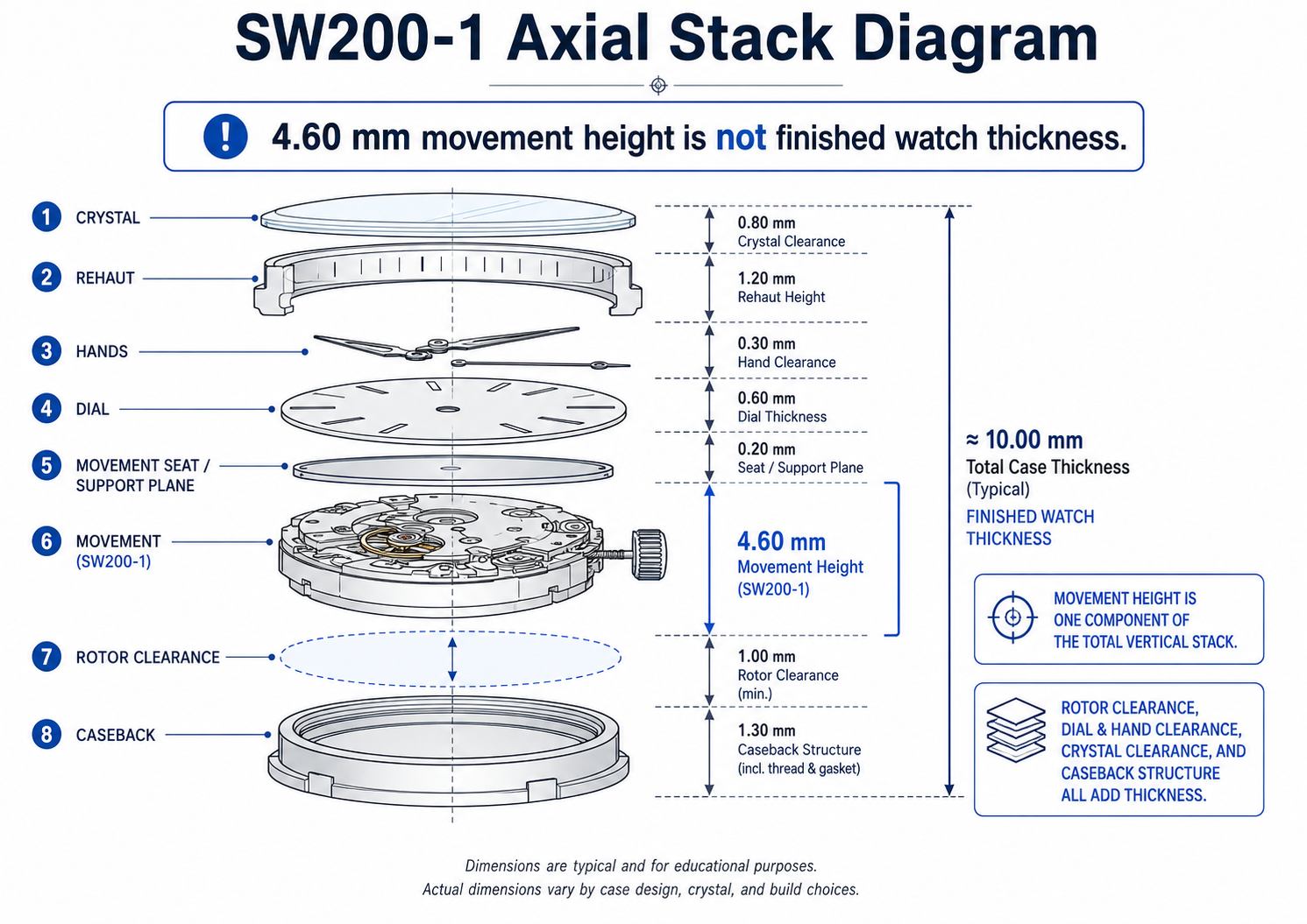
Movement Height and Finished Watch Thickness
The SW200-1 movement height is 4.60 mm.
That dimension represents only one part of the complete watch stack.
Finished thickness must also account for:
- movement seating
- dial support
- dial thickness
- hand-fitting height
- hand-to-hand clearance
- hand-to-crystal clearance
- rehaut depth
- crystal thickness
- crystal retention
- rotor clearance
- caseback internal depth
- caseback wall thickness
- gasket compression
- movement retention
- manufacturing variation
- finishing variation
A case designed around the movement height alone will usually be incorrect.
Potential consequences include:
- rotor contact
- hand contact
- movement compression
- excessive caseback depth
- greater finished thickness than expected
- incorrect crown-axis position
A well-proportioned SW200-1 case is possible.
The complete axial stack must be resolved before the exterior thickness is fixed.
Related engineering reference: Movement Height vs Case Thickness
Axial Stack Control
The axial stack controls the vertical relationship between:
- caseback
- rotor
- movement
- movement seat
- dial
- hands
- rehaut
- crystal
The movement must be protected on both sides.
The caseback side must provide free operating space for the automatic winding system.
The dial side must provide controlled support and clearance for the dial and hands.
Insufficient axial space can cause:
- rotor rubbing
- hand contact
- dial loading
- movement compression
- caseback interference
Excessive uncontrolled space can cause:
- movement lift
- dial movement
- stem misalignment
- retention inconsistency
- impact noise
Axial clearance is not arbitrary empty space.
It is a controlled relationship between real surfaces and their tolerance limits.
Related engineering reference: Axial Clearance
SW200-1 Axial Stack Diagram
Rotor Clearance and Caseback Architecture
The rotor occupies a moving envelope behind the movement.
The caseback cannot be developed only from the desired exterior profile.
Its internal geometry must preserve rotor clearance through:
- movement seating variation
- rotor motion
- rotor endshake
- manufacturing tolerance
- caseback deflection
- gasket compression
- finishing buildup
- shock loading
Insufficient clearance can cause:
- rubbing
- scraping noise
- winding drag
- reduced winding efficiency
- witness marks
- wear debris
- movement damage
A common mistake is to reduce caseback depth in pursuit of a thinner-looking watch without protecting the rotor envelope.
The rotor space should be resolved before the external caseback profile is finalised.
The caseback must then satisfy several requirements simultaneously:
- rotor protection
- structural stiffness
- gasket support
- thread or retention geometry
- service access
- acceptable external proportion
Related engineering reference: Rotor Clearance Requirements
Winding and Functional Test Information
The SW200-1 supports automatic and manual winding.
Sellita also provides controlled winding and test instructions for workshop and production use.
These instructions relate to:
- manual winding through the stem
- powered winding equipment
- testing with the automatic winding system installed
- testing without the automatic system installed
These are servicing and controlled-test procedures rather than everyday user instructions.
For the case designer, the important implications are:
- the crown and stem system must permit smooth manual winding
- the setting stem must remain aligned throughout operation
- the crown must provide suitable access
- the keyless works must not receive lateral load
- the rotor must remain free to operate
- the caseback must not introduce automatic-winding interference
A case can satisfy nominal movement dimensions and still compromise winding performance through poor stem alignment or insufficient rotor clearance.
Stem Axis and Crown-Tube Alignment
The crown position must be derived from the movement stem axis.
It should not be selected visually and joined to the movement afterward.
The stem axis controls:
- case-wall bore position
- crown-tube centreline
- crown seating
- winding feel
- setting feel
- date correction
- keyless-works loading
- crown-gasket alignment
- crown-guard geometry
If the crown tube is misplaced, the stem may be forced into alignment during assembly.
The watch may still operate, but the system can suffer from:
- stem bending
- rough winding
- poor setting feel
- keyless-works side load
- uneven gasket compression
- premature wear
- visibly incorrect crown position
The movement support plane, stem axis, case-wall bore, crown tube, and crown should be developed as one mechanical chain.
The crown is both:
- a user interface
- a sealing interface
Related engineering reference: Crown and Stem Alignment in Watch Cases
Setting-Stem Length and Crown Position
Sellita provides normal and long setting-stem options.
| Setting-stem option | L | L1 | L2 |
|---|---|---|---|
| Normal | 15.50 mm | 8.45 mm | 21.25 mm |
| Long | 20.00 mm | 12.95 mm | 25.75 mm |
The setting-stem thread is identified as S0.90.
These are manufacturer component references.
They do not directly define the final cut length for every case.
Final stem length must be derived from the assembled relationship between:
- movement seating position
- case wall
- crown tube
- crown internal geometry
- winding and setting positions
- gasket arrangement
- screw-down travel where applicable
Sellita states that the gap between the crown and the middle case must not exceed 0.10 mm when the movement is fixed in the case.
The purpose is functional.
An excessive gap can increase the risk that an impact on the crown transfers damaging load through the setting stem into the movement.
The crown-to-middle relationship should therefore be treated as:
- an impact-protection requirement
- a stem-loading consideration
- an operating-position constraint
- a sealing-system relationship
It is not merely an exterior styling gap.
The final stem should never be shortened by visual judgement alone.
Its length should be established using the actual movement, case, tube, and crown assembly.
Related engineering reference: Stem Height to Crown Tube Position Relationship
Screw-Down Crown Operating Positions
Sellita provides a dedicated screw-down crown-position drawing for the documented SW200-1 arrangement.
The total 0.80 mm setting-stem travel is divided into two manufacturer-defined operating segments.
The drawing also includes force references for the illustrated crown mechanism.
These values describe the manufacturer’s documented operating relationship.
They do not prescribe one universal crown, tube, spring, or gasket design for every SW200-1 case.
A project-specific screw-down crown system must still be validated for:
- thread engagement
- crown release
- winding position
- date-correction position
- time-setting position
- spring preload
- gasket compression
- stem alignment
- operating force
Dial Interface and Date-Window Geometry
Sellita provides dedicated dial-interface drawings for the SW200-1.
These define manufacturer relationships for:
- dial retention
- dial support
- centre-hole geometry
- dial-side clearance
- date-disc position
- date-window size
- date-window centre distance
- attachment locations
For the documented date-equipped execution, the revised drawing identifies:
| Feature | Manufacturer reference |
|---|---|
| Dial centre hole | 2.00 mm with stated positive tolerance |
| Dial attachment radius | 11.60 mm |
| Attachment offset | 3.78 mm |
| Dial-to-date-disc relationship | 0.16 mm |
| Revised date-window dimension | 2.30 mm |
| Revised date-window centre distance | 10.40 mm |
These values apply to the documented dial execution.
They should not be assumed to describe every supplier dial, modified calendar arrangement, or custom no-date configuration.
The final dial and case system must coordinate:
- movement concentricity
- rotational orientation
- dial retention
- dial thickness
- centre-hole clearance
- date-window position
- rehaut opening
- chapter-ring geometry
- applied-marker clearance
- hand-stack clearance
Small movement-location errors can become visually obvious at the date aperture.
A movement may remain mechanically operational while the date appears displaced because of:
- radial movement
- rotational movement
- incorrect dial location
- incorrect aperture position
- cumulative tolerance error
The case should not be used to compensate for an incorrectly designed dial.
Movement, dial, date display, and case opening should be developed as one controlled assembly.
Related engineering reference: Dial Integration & Case Interface
Dial Attachment
The Sellita drawing identifies a manufacturer-defined dial-locking arrangement.
The final dial programme must confirm:
- attachment method
- locking geometry
- engagement
- dial thickness
- date-disc clearance
- service release method
The case should not compensate for an incorrectly specified dial.
Movement, dial, and case should be developed as one coordinated assembly.
Changes to dial thickness, attachment position, applied markers, dial construction, or surface build-up may alter the axial stack or assembly process.
Hand-Fitting Heights and Crystal Clearance
Sellita provides eight three-hand fitting-height arrangements for the SW200-1.
Hand-fitting height 2 is identified as the standard arrangement.
Additional heights are available as special configurations.
Sellita also provides a separate table for arrangements without a central seconds hand.
This matters because the selected hand-height execution changes:
- cannon-pinion length
- hour-wheel height
- seconds-pinion height
- hand-seat position
- dial-to-hand relationship
- hand-to-hand spacing
- required rehaut depth
- crystal clearance
- total dial-side stack
The case designer must record the exact hand-fitting-height code before fixing:
- dial thickness
- applied-marker height
- rehaut geometry
- hand profile
- crystal underside position
“SW200-1 hand height” is not one universal dimension.
It is a selected manufacturer execution.
The complete system must protect against contact between:
- hour hand and dial
- minute hand and hour hand
- seconds hand and minute hand
- hands and applied markers
- hands and rehaut
- upper hand and crystal
Movement fit, rotor clearance, and crown alignment can all be correct while the watch still fails because of hand contact.
Related engineering references: Hand Stack Height and Clearance Requirements; Dial to Crystal Clearance
Detailed Hand-Height Data
The complete manufacturer hand-height tables should be made available through:
- an expandable technical-reference section
- a separate HorologyCAD reference table
- or direct consultation of the official Sellita document
The main article should identify the standard Height 2 execution without overwhelming the introductory specification layer.
Movement Holder and Retention Strategy
The SW200-1 must be retained securely without being:
- distorted
- pinched
- allowed to shift
- allowed to rotate
A complete retention system should control:
- radial movement
- axial movement
- rotation
- dial alignment
- stem loading
- shock response
- service removal
Possible strategies include:
- manufacturer-style casing clamps
- dedicated movement holder
- casing ring
- spacer ring
- locating shoulders
- combined locating and retention geometry
The correct method depends on:
- case material
- machining method
- production quantity
- assembly order
- water-resistance target
- dial architecture
- service strategy
The movement should not be trapped accidentally between the dial side and caseback.
The caseback should not become the sole retention feature unless the full axial stack has deliberately been engineered for that role.
Retention must be controlled.
It should not depend on unknown compression.
Related engineering reference: Movement Securing Methods
Setting-Stem Removal and Service Access
Sellita defines a specific procedure for removing the SW200-1 setting stem.
The movement should first be placed in the time-setting position.
The setting-lever axis is then pressed using a 1.00 mm screwdriver before the stem is withdrawn.
Sellita warns against using pointed tools such as tweezers because excessive or poorly controlled pressure may jam the setting lever or damage the setting-lever spring.
This procedure creates a direct case-design requirement.
The case architecture should provide:
- visible access to the release point
- sufficient screwdriver approach
- adequate clearance around the movement
- stable support during stem removal
- a service sequence that avoids levering against finished surfaces
The release point should not be hidden behind:
- an inaccessible holder
- a case-wall obstruction
- a casing clamp
- a decorative internal feature
- an assembly sequence that traps the movement
A case may hold the movement securely and still be poorly engineered if the stem cannot be removed safely.
Service access must be reviewed during CAD development.
Sealing and Water-Resistance Architecture
Water resistance must be integrated into the movement-led case architecture from the beginning.
The case must coordinate:
- crown sealing
- crown-tube alignment
- caseback sealing
- crystal sealing
- gasket compression
- thread engagement
- sealing-surface finish
- structural stiffness
- axial-stack behaviour
- service replacement
The crown is both an operating interface and a sealing interface.
A misplaced crown tube can compromise crown feel and gasket function simultaneously.
The caseback must preserve rotor clearance while also supporting:
- gasket compression
- sufficient wall thickness
- thread or retention structure
- repeatable assembly
- service access
Water resistance is not added after movement fit is complete.
It is part of the same engineering system.
Related engineering references: Water Resistance Engineering in Watch Cases; Caseback Sealing System
Manufacturing and Tolerance Strategy
A CAD model can appear correct while remaining difficult or impossible to manufacture consistently.
The case architecture must account for:
- tool access
- cutter radius
- bore accuracy
- concentricity
- flatness
- perpendicularity
- thread geometry
- finishing removal
- coating buildup
- inspection method
- component variation
- assembly variation
Every critical interface should have:
- nominal dimension
- tolerance
- functional purpose
- inspection method
The designer should be able to explain:
- what locates the movement
- what retains it
- what prevents rotation
- what controls the stem axis
- what protects the rotor
- what supports the dial
- what establishes hand clearance
- what compresses each gasket
- how each relationship will be inspected
If a critical feature cannot be measured or inspected, its production control is weak.
Related engineering references: Watch Case Tolerances; CNC Machining Constraints in Watch Cases
Assembly and Service Access
A professional case must allow the movement to be installed, tested, removed, and recased without damage.
The assembly sequence should define:
- how the movement and dial assembly enter the case
- how the setting stem is inserted
- how the setting stem is removed
- how the holder or clamps are installed
- how rotation is controlled
- how axial retention is applied
- how rotor clearance is checked
- how crown functions are tested
- how sealing components are installed
- how the watch is reopened for service
A design requiring excessive force, component distortion, inaccessible screws, or destructive disassembly is not fully resolved.
Serviceability is an engineering requirement.
Physical-Sample Validation
Manufacturer documentation establishes the nominal technical basis.
Physical inspection confirms the actual components entering the project.
Before final CAD release, compare the documentation with:
- physical SW200-1 movement
- selected dial
- intended hand set
- setting stem
- crown
- crown tube
- casing clamps
- movement holder
- prototype components
Where practical, inspect:
- overall movement envelope
- case-fitting region
- movement height
- stem-axis relationship
- setting-stem travel
- rotor envelope
- dial interface
- clamp geometry
- hand-height execution
Physical measurements should not casually override official drawings.
Measurement uncertainty, access limitations, and component condition must be considered.
Where the drawing, supplier information, and physical component appear to disagree:
- stop the design release
- identify the discrepancy
- verify document revision
- confirm movement execution
- consult the supplier or manufacturer where necessary
- record the resolution
An unresolved discrepancy should not be hidden inside an arbitrary clearance.
Common SW200-1 Case-Design Mistakes
Treating the movement as a single 25.60 mm cylinder
The movement has a broader 26.00 mm envelope and additional stepped geometry.
Machining the cavity at exactly 25.60 mm
This ignores the actual locating interface, assembly method, tolerances, and finishing allowance.
Treating 4.60 mm as the finished watch thickness
Movement height excludes the dial, hands, crystal, rotor clearance, caseback, and sealing architecture.
Selecting the crown position visually
The crown tube must be positioned from the movement stem axis.
Guessing setting-stem length
Stem length must be derived from the actual case, tube, and crown system.
Ignoring the crown-to-middle limit
The manufacturer’s maximum-gap instruction is an impact-protection requirement, not only a visual consideration.
Ignoring hand-fitting height
Different hand-height executions alter the required dial-to-crystal stack.
Reducing caseback depth without checking the rotor
A thin external profile can create rotor interference.
Using the stem as an anti-rotation feature
The setting stem should not carry structural locating loads.
Relying on caseback compression to retain the movement
Retention should be deliberate and repeatable.
Ignoring date-window alignment
Small radial or rotational errors can create obvious visual displacement.
Assuming ETA 2824-2 interchangeability
Nominal similarity does not prove compatibility across every casing interface.
Adding sealing geometry after the case is designed
Sealing affects wall thickness, axial stack, threads, and crown alignment.
Blocking setting-stem release access
A secure casing system is still poor if the stem cannot be removed safely.
Designing without an assembly sequence
A component can fit in CAD but remain impossible to install or service.
Treating one successful prototype as production proof
A working prototype demonstrates possibility.
Production requires repeatability.
Service Ecosystem and Long-Term Use
The SW200-1 benefits from broad watchmaker familiarity and an established servicing context.
It is suitable for watches intended to be:
- maintained
- regulated
- repaired
- recased
- retained long term
Serviceability also imposes case-design requirements.
A well-resolved case should permit:
- controlled stem removal
- access to retention features
- holder or clamp removal
- non-destructive movement extraction
- gasket replacement
- reliable recasing
- functional checks after assembly
A case that cannot be serviced cleanly is not fully engineered.
Collector and Product Perception
Collectors generally understand the SW200-1 as a familiar and serviceable Swiss automatic movement rather than a rare or exotic calibre.
That perception depends heavily on the finished watch.
In a poorly resolved watch, the movement may feel generic.
In a well-engineered watch, it can feel:
- dependable
- maintainable
- appropriately specified
- professionally integrated
- suitable for the product
Movement prestige cannot compensate for:
- poor crown action
- rotor contact
- excessive thickness
- weak retention
- poor sealing
- poor dial alignment
- inconsistent assembly
The quality of integration determines whether the movement feels ordinary or correctly applied.
SW200-1 Ecosystem and Related Movements
The SW200-1 is often compared with the ETA 2824-2 because both occupy the same broad 11½-ligne Swiss automatic category.
That comparison is useful for:
- movement selection
- general dimensional context
- service familiarity
- product planning
It does not establish universal interchangeability.
The final case must still be checked against:
- exact calibre
- execution
- current technical drawing
- overall envelope
- casing frame
- dial interface
- date configuration
- hand-fitting height
- setting stem
- holder and clamp arrangement
The SW200-1 should also be understood within a broader movement ecosystem that may include:
- ETA 2824-2 — a historically important reference point for this category
- Sellita SW200-1 — the calibre covered by this page
- Sellita SW300-1 — a thinner Sellita movement family requiring separate case architecture
- Sellita SW400-1 — a larger related Sellita movement family requiring separate dimensional validation
Similar naming, similar function, or similar nominal diameter does not prove casing compatibility.
The word “compatible” should never replace dimensional verification.
What the SW200-1 Does Not Decide
The movement does not define:
- final case diameter
- bezel design
- lug geometry
- case-wall thickness
- crown shape
- crown-tube installation
- caseback profile
- gasket selection
- crystal system
- rehaut depth
- dial opening
- finishing specification
- machining strategy
- external proportion
A proven movement reduces one category of uncertainty.
It does not replace case engineering.
The movement establishes the internal reference.
The designer must convert that reference into:
- controlled geometry
- tolerance behaviour
- assembly logic
- inspection criteria
- prototype validation
- repeatable production architecture
SW200-1 Pre-Prototype Verification Checklist
Before releasing the case for prototyping, confirm that:
- physical calibre is identified as SW200-1
- exact execution is recorded
- technical-document revision is recorded
- overall 26.00 mm envelope is understood
- applicable 25.60 mm casing fit is identified
- stepped movement geometry is accommodated
- date arrangement is confirmed
- hand-fitting-height execution is confirmed
- dial specification is confirmed
- dial attachment is confirmed
- date aperture is coordinated
- setting-stem option is confirmed
- crown system is confirmed
- crown-to-middle maximum is reviewed
- locating datum is defined
- radial locating interface is defined
- holder or casing-ring system is defined
- clamp type and screw are defined
- stem-release access is preserved
- anti-rotation control is defined
- radial tolerances are assigned
- axial tolerances are assigned
- rotor clearance is protected
- caseback clearance is checked at worst case
- stem axis is transferred into the case datum system
- crown-tube alignment is verified
- crown positions are verified
- dial-seat height is controlled
- hand-to-hand clearance is protected
- hand-to-dial clearance is protected
- hand-to-marker clearance is protected
- hand-to-rehaut clearance is protected
- hand-to-crystal clearance is protected
- movement lift is controlled
- movement rotation is controlled
- gasket compression does not compromise movement clearance
- machining allowances are included
- finishing allowances are included
- inspection methods exist
- assembly order has been reviewed
- service removal is possible
- physical-sample inspection is recorded
- representative production components will be used in the prototype
This checklist does not replace production drawings or prototype testing.
It controls the principal movement-to-case risks before manufacture begins.
Movement-Led SW200-1 Case-Design Workflow
1. Confirm the movement
Identify the exact calibre, execution, date arrangement, grade, hand height, and supplied components.
2. Secure the official documentation
Record the document title, revision, date, and source.
3. Create the project movement record
Record the physical marking, supplier, dial, hands, stem, holder, clamps, and crown system.
4. Extract manufacturer geometry
Review the 26.00 mm envelope, 25.60 mm case-fitting reference, stepped casing geometry, dial interface, hand heights, stem information, and crown guidance.
5. Inspect the physical components
Compare the actual movement and selected parts against the documented specification.
6. Select the locating architecture
Define which component establishes position.
7. Resolve radial fit
Allocate clearance and tolerance at the selected locating interface.
8. Resolve anti-rotation
Provide rotational control independent of the setting stem.
9. Resolve the axial stack
Build the complete stack from caseback to crystal.
10. Protect the rotor
Resolve internal caseback geometry before fixing the exterior profile.
11. Transfer the stem axis
Position the case-wall bore and crown tube from the movement datum system.
12. Resolve the crown system
Establish stem length, operating positions, tube projection, crown-to-middle gap, and gasket behaviour.
13. Resolve dial and hands
Coordinate dial seat, revised date aperture, selected hand height, rehaut, and crystal.
14. Define retention
Control radial movement, axial lift, and rotation without distorting the movement.
15. Preserve stem-removal access
Ensure the setting-lever release remains safely accessible.
16. Integrate sealing
Coordinate crown, crystal, and caseback sealing with the existing architecture.
17. Apply tolerances
Assign tolerances and inspection methods to all critical interfaces.
18. Validate assembly and service
Confirm that the watch can be assembled, opened, and serviced without damage.
19. Build and inspect the prototype
Use representative components and record deviations from CAD.
This sequence prevents the common mistake of designing the exterior first and forcing the movement into the remaining space.
Prototype Validation
The first prototype is an engineering test article.
After assembly, verify that:
- movement enters without forced seating
- holder or casing ring remains undistorted
- casing clamps seat correctly
- clamp screws remain accessible
- setting-stem release remains accessible
- movement cannot shift radially
- movement cannot rotate
- movement cannot lift axially
- stem enters without lateral deflection
- winding is smooth
- time setting is smooth
- date correction operates correctly
- crown positions are distinct
- crown-to-middle relationship is controlled
- dial remains centred
- date aperture remains aligned
- hands clear one another
- hands clear the dial
- hands clear applied markers
- hands clear the rehaut
- hands clear the crystal
- rotor rotates freely
- no caseback witness marks appear
- no abnormal rotor noise is present
- caseback sealing does not reduce rotor clearance
- crown and crystal sealing function as intended
- case can be reopened
- movement can be removed
- movement can be recased repeatably
Where appropriate, repeat checks:
- dial up
- dial down
- crown up
- crown down
- before final caseback tightening
- after final assembly
- after sealing tests
- after reopening and recasing
Prototype Measurement Record
For each prototype, record:
- prototype revision
- CAD revision
- technical-document revision
- movement identification
- movement grade
- dial identification
- hand-set identification
- hand-height execution
- crown and tube identification
- stem option
- holder or clamp revision
- radial-interface measurement
- movement seating position
- caseback clearance
- dial position
- date-window alignment
- hand clearances where practical
- winding observations
- setting observations
- sealing-test result
- failed checks
- corrective action
- final disposition
Possible dispositions include:
- accepted
- accepted with controlled deviation
- rework required
- redesign required
- rejected
A prototype should not be accepted merely because it can be assembled.
Acceptance requires correct location, free operation, serviceability, and conformity with the intended engineering requirements.
Production Acceptance Criteria
Before approving the architecture for production, confirm that:
- critical dimensions have tolerances
- tolerances reflect the manufacturing process
- inspection methods exist
- worst-case conditions have been reviewed
- movement installation is repeatable
- movement retention is repeatable
- stem access is repeatable
- crown function is repeatable
- rotor clearance is repeatable
- dial and date alignment are repeatable
- hand clearance is repeatable
- sealing is repeatable
- disassembly and recasing are repeatable
- approved deviations are documented
- production samples match the approved prototype
One successful prototype proves possibility.
Production approval requires repeatability.
Related HorologyCAD Engineering Pages
Continue through the movement-led case-design system.
Start With Movement Fit
Define Clearance and Case Architecture
Resolve Crown, Stem, Dial, and Hands
- Crown and Stem Alignment in Watch Cases
- Stem Height to Crown Tube Position Relationship
- Dial Integration & Case Interface
- Hand Stack Height and Clearance Requirements
- Dial to Crystal Clearance
Control Retention, Sealing, and Manufacturing
- Movement Securing Methods
- Water Resistance Engineering in Watch Cases
- Caseback Sealing System
- Watch Case Tolerances
- CNC Machining Constraints in Watch Cases
Continue the SW200-1 Cluster
- SW200-1 Case Design Constraints
- SW200-1 Case Design Guide
- SW200-1 Case Core: Movement-Fit CAD System
- SW200-1 vs NH35 vs Miyota 9015
HorologyCAD Design Position
The Sellita SW200-1 is not merely a list of specifications.
It is a fixed internal engineering system around which the watch case must be developed.
Its overall envelope, case-fitting diameter, movement height, stem axis, dial interface, hand-fitting execution, rotor, and retention requirements all influence the finished watch.
When those relationships are interpreted correctly, the designer can create a case that:
- assembles predictably
- locates the movement accurately
- controls rotation
- protects the automatic system
- aligns the crown and stem
- preserves dial and hand clearance
- supports water resistance
- controls manufacturing variation
- can be inspected
- remains serviceable
The principle is straightforward:
Begin with verified manufacturer data, establish the internal case architecture, validate it using real components, and develop the exterior around a mechanically resolved system.
Next Step
For the complete movement-to-case relationship:
For movement-cavity sizing and location logic:
→ Internal Case Geometry & Movement Cavity Sizing
For SW200-1-specific failure boundaries:
→ SW200-1 Case Design Constraints
Return to HorologyCAD
HorologyCAD is a movement-led watch case design system for developing case architecture around real mechanical movements, manufacturable constraints, and functional assembly requirements.
→ Movement-Led Watch Case Design & Engineering
Technical Note
This page is based on Sellita SW200-1 technical documentation, Revision 07, dated 2 September 2024.
Last checked against the identified manufacturer documentation: 21 June 2026.
Manufacturer data should always be checked against the current official Sellita documentation and the exact movement execution used in the project.
HorologyCAD engineering guidance on case geometry, clearance, retention, stem alignment, sealing, assembly and validation is interpretive design guidance. Final case architecture should be confirmed against physical components, prototype assembly and production inspection.