
The Sellita SW300-1 is an 11½-ligne Swiss automatic mechanical movement used in refined, slim, independent, premium, and modern production watches.
For watch case design, the SW300-1 should not be treated as a simple thin movement with a diameter and height. It is a fixed internal mechanical system with a defined casing envelope, stem-axis relationship, dial-side architecture, rotor clearance requirement, hand-height dependency, date or no-date execution, movement-retention needs, sealing constraints, and service-access requirements.
The headline dimensions identify the movement.
They do not define the finished watch case.
A professional SW300-1 case must resolve four linked engineering groups:
- movement location, holder strategy, anti-rotation, and retention
- radial clearance, axial clearance, rotor clearance, and caseback stiffness
- stem-axis, crown and stem alignment, dial, date, hand-height, rehaut, and crystal relationships
- sealing, tolerances, assembly, inspection, prototype validation, and service access
HorologyCAD treats the SW300-1 as a benchmark movement for slim movement-led watch case design because it demonstrates a critical engineering problem:
A thin movement does not automatically create a thin watch.
The SW300-1 gives the designer a lower internal movement height than many standard automatic calibres, but the advantage is preserved only if the surrounding case architecture is resolved efficiently. Rotor space, caseback stiffness, crown alignment, hand clearance, sealing geometry, and tolerance control can easily consume the apparent thickness benefit if they are handled late or casually.
This page separates two information layers:
Official Sellita Manufacturer Data
Specifications, dimensions, movement functions, technical relationships, and casing references defined by Sellita documentation.
HorologyCAD Engineering Interpretation
Case-design guidance explaining how those manufacturer references affect movement location, radial clearance, axial clearance, rotor clearance, crown and stem alignment, hand clearance, sealing, manufacturability, assembly, serviceability, and prototype validation.
Manufacturer documentation defines the movement.
HorologyCAD explains what that movement requires from the case.
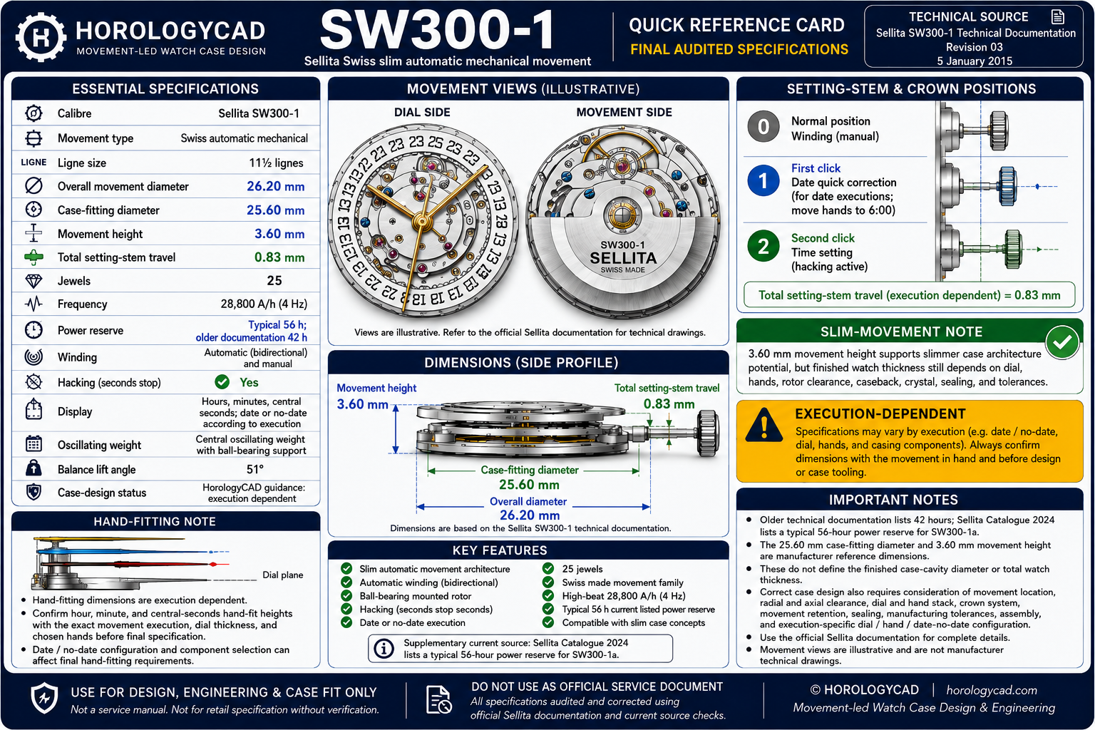
SW300-1 Quick Reference
| Specification | Manufacturer reference |
|---|---|
| Calibre | Sellita SW300-1 |
| Movement type | Swiss automatic mechanical |
| Ligne size | 11½ lignes |
| Overall movement diameter | Verify against exact SW300-1 execution / current technical document |
| Case-fitting diameter | 25.60 mm |
| Movement height | 3.60 mm |
| Frequency | 28,800 A/h / 4 Hz |
| Jewels | 25 |
| Running time | 42 hours in older technical documentation; later/current executions may be listed around 56 hours |
| Winding | Automatic and manual |
| Stop seconds | Yes |
| Display | Central hours, minutes, and seconds; date or no-date depending on execution |
| Date correction | Quick correction in documented date executions |
| Oscillating weight | Central rotor with ball-bearing support |
| Balance lift angle | 51° |
| Standard design role | Slim Swiss automatic movement |
| Case-design status | Execution dependent |
Ligne Size Note
The ligne is a traditional Swiss and French watchmaking unit used to classify movement size. One ligne equals 2.2558 mm, although ligne classifications are nominal and should not be treated as controlling engineering dimensions.
For watch-case design and CAD development, use the movement’s official metric dimensions rather than the ligne classification.
SW300-1 Quick Reference Card
The 25.60 mm case-fitting diameter and 3.60 mm movement height are important manufacturer references.
They are not a finished case design.
The 25.60 mm dimension identifies the principal manufacturer-defined casing-fit reference.
The 3.60 mm movement height identifies the movement height, not the final watch thickness.
Final case geometry must additionally account for:
- locating surfaces
- holder or casing-ring geometry
- assembly clearance
- anti-rotation control
- movement-retention features
- dial support
- dial thickness
- selected hand height
- hand-to-crystal clearance
- rotor clearance
- caseback internal depth
- caseback stiffness
- crown and stem alignment
- crown-tube support
- gasket systems
- crystal retention
- manufacturing variation
- finishing allowance
- service access
A movement dimension becomes useful only when its function within the complete watch system is understood.
SW300-1 Quick Reference Card
Official Manufacturer Source
| Item | Reference |
|---|---|
| Manufacturer | Sellita Watch Co. SA |
| Calibre | SW300-1 |
| Primary document | Sellita SW300 / SW300-1 Technical Documentation |
| Current HorologyCAD source status | Manufacturer documentation identified and checked |
| HorologyCAD archive reference | HC-MTS-SW300-1 |
The official Sellita technical document is the primary source for manufacturer-defined information on this page.
It contains information relating to:
- movement specifications
- winding and testing
- timing and performance criteria
- component identification
- movement assembly
- automatic winding assembly
- casing components
- casing clamps
- dial fastening
- calendar display
- setting-stem positions
- oscillating weight
- fine regulation
- movement diameter
- case-fitting diameter
- movement height
- frequency
- running time
- jewel count
- balance lift angle
Where information is described as official manufacturer data, it should be traceable to the relevant Sellita document section.
The technical document does not remove the need to inspect the exact movement and components used in the project.
Manufacturer-Document Use
The original Sellita technical documentation should be linked for attribution and verification.
The manufacturer drawings contain protected technical material. HorologyCAD should therefore not reproduce complete Sellita drawings without the appropriate permission.
HorologyCAD technical visuals and explanations should be:
- independently created
- clearly source-attributed
- based on verified manufacturer references
- explanatory rather than copied
- labelled according to source status
This maintains a clear distinction between:
- Sellita documentation
- HorologyCAD engineering interpretation
- HorologyCAD original explanatory material
Readers should consult the original manufacturer document for the complete Sellita specification.
Verification and Revision Notes
| Item | Status |
|---|---|
| Manufacturer | Sellita Watch Co. SA |
| Calibre | SW300-1 |
| Primary source | Sellita SW300 / SW300-1 Technical Documentation |
| Initial HorologyCAD source review | 22 June 2026 |
| Manufacturer documentation audit | Completed against identified available technical documentation |
| Physical movement validation | Pending |
| Prototype validation | Pending |
| Page status | Manufacturer-documentation audited flagship draft |
Verification Scope
The manufacturer specifications and principal case-integration relationships used on this page have been checked against identified Sellita SW300 / SW300-1 technical documentation.
The audit covers:
- headline specifications
- case-fitting diameter
- movement height
- frequency
- jewel count
- running time in the identified document
- balance lift angle
- basic movement functions
- date-window execution
- setting-stem positions
- oscillating-weight description
- stop-seconds function
- fine timing device
- winding-test information
- movement-grade context
- casing-clamp and component references where identifiable
HorologyCAD guidance concerning finished cavity sizing, holder strategy, radial clearance, axial clearance, anti-rotation, caseback architecture, rotor protection, sealing, tolerances, assembly, inspection, slim-case stiffness, and prototype acceptance is engineering interpretation.
It is not a universal set of Sellita-prescribed case dimensions.
Configuration Warning
Final case geometry must be checked against:
- physical calibre marking
- exact SW300-1 execution
- current technical document
- date or no-date configuration
- selected hand-fitting height
- dial construction
- setting-stem option
- casing-clamp or holder arrangement
- crown and tube system
- actual movement sample where practical
Nominal similarity to the ETA 2892-A2, Sellita SW200-1, ETA 2824-2, or another 11½-ligne Swiss automatic movement does not prove complete casing interchangeability.
Power-Reserve Warning
Older SW300-1 technical references identify a 42-hour running time.
Later or current SW300-family executions may be encountered with longer quoted running times, including around 56 hours depending on execution and supplier documentation.
Power reserve should therefore be treated as execution- and document-dependent.
For case design, this distinction usually affects specification, procurement, product positioning, and movement identification more than the basic movement-to-case envelope.
The exact movement execution should still be recorded before CAD release.
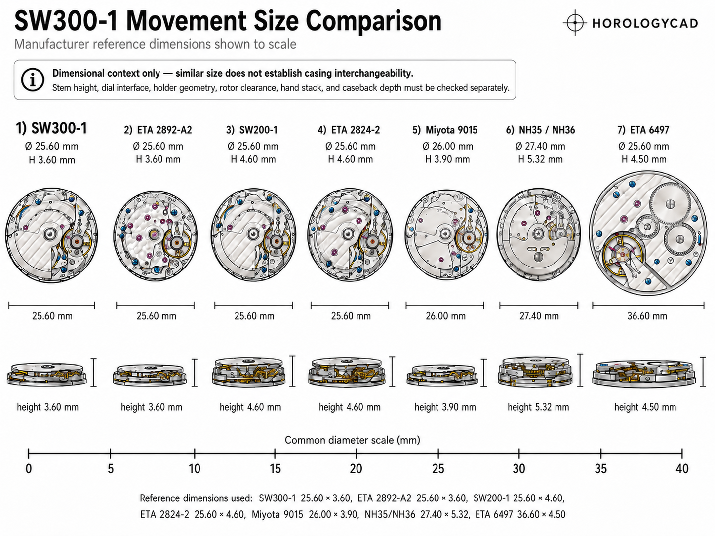
SW300-1 Compared With Other Common Watch Movements
The SW300-1 is one of several common automatic movements used in modern watch case design.
Comparing it with alternatives such as the Sellita SW200-1, ETA 2824-2, ETA 2892-A2, Miyota 9015, and Seiko NH35 / NH36 helps show why movement diameter, height, stem position, rotor clearance, and caseback architecture must be considered before the external case shape is finalised.
The SW300-1 shares a similar broad diameter class with several Swiss 11½-ligne automatic movements, but its 3.60 mm movement height places it in a slim automatic category.
That distinction is central to the case-design problem.
The SW300-1 is not simply a smaller SW200-1.
It is a different vertical packaging opportunity.
SW300-1 Compared With Other Common Movements
Technical Source Classification
The following hierarchy applies throughout this page.
- Level A — Direct Manufacturer Specification
- Level B — Manufacturer Drawing Interpretation
- Level C — Execution-Dependent Manufacturer Information
- Level D — HorologyCAD Engineering Interpretation
- Level E — Project-Specific Validation
Level A means a value stated explicitly in official Sellita documentation.
Level B means a dimension or relationship read directly from an official Sellita technical drawing.
Level C means a value or relationship that may change according to movement execution, date arrangement, no-date execution, dial configuration, hand-fitting height, supplied stem, or casing components.
Level D means case-design guidance developed from manufacturer information and movement-led engineering principles.
Level E means a relationship requiring confirmation through selected components, physical measurements, tolerance analysis, prototype assembly, functional testing, or production inspection.
Level D and Level E information must not be represented as official Sellita specifications.
Manufacturer Data Register
| Data item | Manufacturer reference | Source class |
|---|---|---|
| Calibre | SW300-1 | Level A |
| Movement family | SW300 | Level A / C |
| Case-fitting diameter | 25.60 mm | Level A / B |
| Movement height | 3.60 mm | Level A |
| Frequency | 28,800 A/h / 4 Hz | Level A |
| Jewel count | 25 | Level A |
| Running time | 42 hours in older technical documentation; later/current executions may differ | Level A / C |
| Balance lift angle | 51° | Level A |
| Display | Central hours, minutes, seconds; date or no-date depending on execution | Level A / C |
| Winding | Automatic and manual | Level A |
| Stop seconds | Yes | Level A |
| Fine timing device | Yes in documented technical references | Level A |
| Oscillating weight | Central rotor with ball-bearing support | Level A / B |
| Setting-stem positions | Execution dependent | Level A / C |
| Casing components | Execution dependent | Level B / C |
| Dial fastening | Execution dependent | Level B / C |
| Date or no-date execution | Execution dependent | Level C |
| Hand-fitting height | Execution dependent | Level C |
| Movement-holder strategy | Project specific | Level D / E |
| Finished case cavity | Project specific | Level D / E |
| Rotor clearance allowance | Project specific | Level D / E |
| Crown-tube position | Derived from movement stem axis and case datum system | Level B / D / E |
Every numerical value used in released production CAD should be checked against:
- applicable drawing page
- document revision
- exact movement execution
- drawing convention
- stated tolerance
- physical movement sample where practical
Where a drawing is unclear, an inference should not be presented as confirmed manufacturer data.
Record Before Beginning CAD
Before developing the case, create a project-specific movement record.
Record:
- manufacturer
- calibre
- physical movement marking
- movement grade
- supplier
- purchase date
- date or no-date execution
- hand-fitting-height code
- dial specification
- dial thickness
- dial attachment
- intended hand set
- setting-stem option and reference
- selected casing clamp
- clamp bend and length
- clamp screw type
- movement-holder strategy
- crown type
- crown-tube architecture
- manufacturer-document revision
- physical measurements
- known component deviations
- CAD revision
- prototype revision
A movement should not be represented only by a vague project label such as “SW300 case.”
The project record should identify the exact movement and component configuration around which the case is being developed.
Why the SW300-1 Matters
The SW300-1 occupies an important position in practical slim Swiss automatic watchmaking.
Its value does not come from being exotic.
It comes from offering:
- Swiss automatic architecture
- a slim 3.60 mm movement height
- a familiar 11½-ligne diameter class
- modern 4 Hz operation
- automatic and manual winding
- stop-seconds functionality
- date and no-date possibilities depending on execution
- premium movement positioning
- service familiarity
- suitability for refined independent watches
- strong relevance to ETA 2892-A2-style case architecture
The SW300-1 is frequently selected because it gives a designer the opportunity to reduce finished case thickness while retaining a conventional central-rotor automatic layout.
That opportunity is real.
It is not automatic.
Poor SW300-1 integration can produce:
- unnecessary finished thickness
- rotor contact
- weak caseback stiffness
- poor crown and stem alignment
- rough winding
- poor setting feel
- weak movement retention
- date-window misalignment
- dial displacement
- insufficient hand clearance
- fragile crown-tube support
- compromised sealing
- difficult assembly
- poor service access
A correctly integrated SW300-1 can produce a watch that feels refined, slim, controlled, and professionally resolved.
The difference lies in the surrounding architecture.
Sellita and the SW300 Family
The SW300 family belongs to Sellita’s slim automatic movement category.
Sellita is a Swiss movement manufacturer based in La Chaux-de-Fonds, an important centre of Swiss watchmaking. The company became especially important to the wider watch industry as independent and non-integrated brands sought reliable Swiss mechanical movements outside fully in-house production.
Within that context, the SW300 family provides a slim Swiss automatic option for brands requiring a lower-profile movement architecture than standard-height automatic calibres.
The SW300-1 should be understood as a slim automatic platform.
It should not be described merely as a thinner SW200-1.
The SW200-1 and SW300-1 occupy different vertical packaging categories:
- the SW200-1 represents standard-height Swiss automatic architecture
- the SW300-1 represents slim Swiss automatic architecture
This distinction matters because movement height affects:
- finished case thickness
- caseback depth
- rotor clearance
- dial-side packaging
- hand-to-crystal clearance
- crown-tube position
- structural wall allocation
- movement-holder design
- sealing architecture
- caseback stiffness
The SW300-1 allows thinner watch-case architecture only when these relationships are deliberately controlled.
Current Calibre Status
This page covers the Sellita SW300-1.
The SW300 family includes multiple related executions and derivative movement families.
Some related movements may include:
- date executions
- no-date executions
- GMT variants
- small-seconds variants
- skeletonised executions
- other display or complication-based derivatives
These related movements may alter:
- total height
- dial-side geometry
- hand stack
- crown settings
- caseback requirements
- movement-holder geometry
- date or display position
The existence of a movement family does not imply automatic interchangeability.
Every execution requires its own technical review.
An SW300-1 project must be validated against SW300-1 documentation and the actual movement supplied for the project.
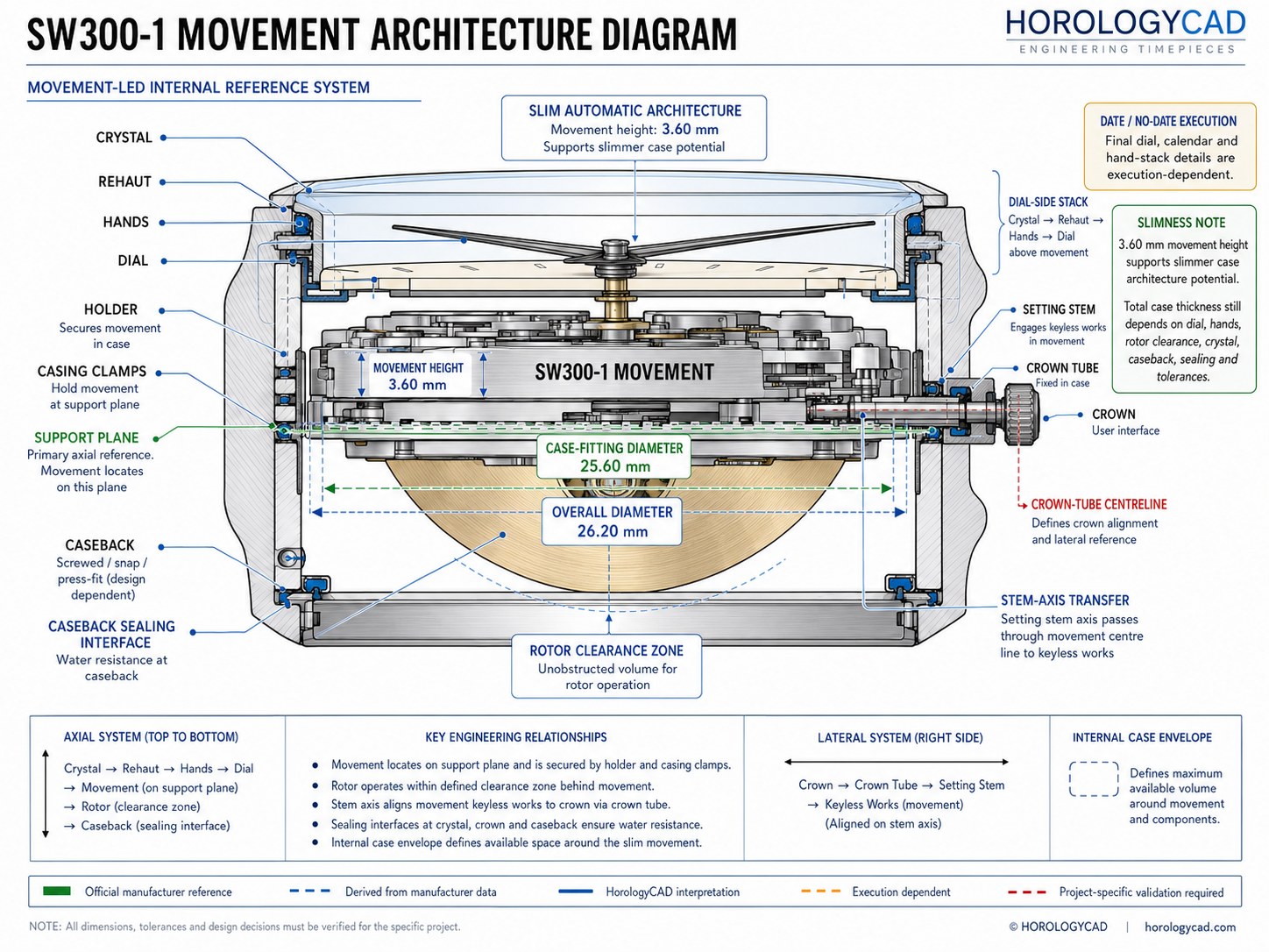
Movement Architecture
The documented SW300-1 execution provides:
- central hours
- central minutes
- central seconds
- date through a window in the documented date execution
- quick date correction in the documented date execution
- automatic winding
- manual winding
- stop seconds
- fine timing device
- central oscillating weight
- ball-bearing rotor support
- conventional dial-side hand and calendar architecture
The architecture is slim.
It is not mechanically simple from a case-design standpoint.
The case designer must coordinate:
- overall movement envelope
- case-fitting diameter
- stepped movement geometry
- locating surfaces
- holder or casing ring
- casing clamps
- dial attachment
- date display where applicable
- selected hand stack
- setting stem
- keyless works
- crown tube
- crown
- rotor envelope
- caseback
- caseback stiffness
- rehaut
- crystal
- gaskets
The SW300-1 is selected partly because it is thin.
That makes careless case design more visible, not less important.
SW300-1 Movement Architecture Diagram
Movement Grades and Timing Performance
Sellita identifies movement-grade and timing-performance distinctions in its technical documentation and supply structure.
Movement grade should not be confused with movement variant.
A grade principally concerns:
- regulation
- positional performance
- quality-control limits
- component selection
- finishing
- commercial positioning
A movement variant or execution may affect physical case integration through:
- calendar arrangement
- no-date configuration
- hand-fitting height
- display system
- dial geometry
- supplied casing components
Manufacturer timing criteria are useful for:
- movement specification
- procurement
- quality control
- regulation expectations
- final product positioning
They do not change the basic case-design requirement to control the 25.60 mm case-fitting diameter, 3.60 mm movement height, rotor clearance, stem axis, and dial-side stack.
The exact grade should nevertheless be recorded in the project movement register.
Appropriate Applications and Limitations
The SW300-1 offers a practical balance of:
- Swiss manufacture
- slim automatic architecture
- serviceability
- supplier relevance
- premium positioning
- familiar 11½-ligne format
- modern 4 Hz operation
It is particularly appropriate for:
- slim automatic watches
- refined sports watches
- premium dress watches
- lower-profile dive watches
- compact Swiss automatic cases
- premium independent watches
- watches where Swiss movement positioning matters
- designs where finished case thickness is a central objective
It is less naturally suited to projects centred on:
- lowest possible movement cost
- very large tool-watch architecture where slimness provides little benefit
- cases where structural stiffness cannot be preserved
- projects where a thicker, cheaper, or more robust workhorse calibre is more appropriate
- designs where the thin movement is offset by an unnecessarily deep caseback, tall dial-side stack, or thick crystal system
These are application boundaries rather than defects.
The movement should be selected because it suits the intended watch architecture.
Movement thinness cannot compensate for weak case integration.
From Manufacturer Data to Case Architecture
Manufacturer documentation tells the designer what the movement is.
It does not completely determine how the watch case should be built.
The case designer must still establish:
- locating datums
- cavity strategy
- holder geometry
- casing-clamp use
- radial clearance
- anti-rotation
- axial retention
- stem-axis transfer
- crown-tube geometry
- rotor protection
- caseback depth
- caseback stiffness
- dial support
- hand clearance
- crystal clearance
- sealing
- tolerances
- assembly
- inspection
- service removal
The central HorologyCAD principle is:
A movement dimension becomes useful only when its role within the complete watch system is understood.
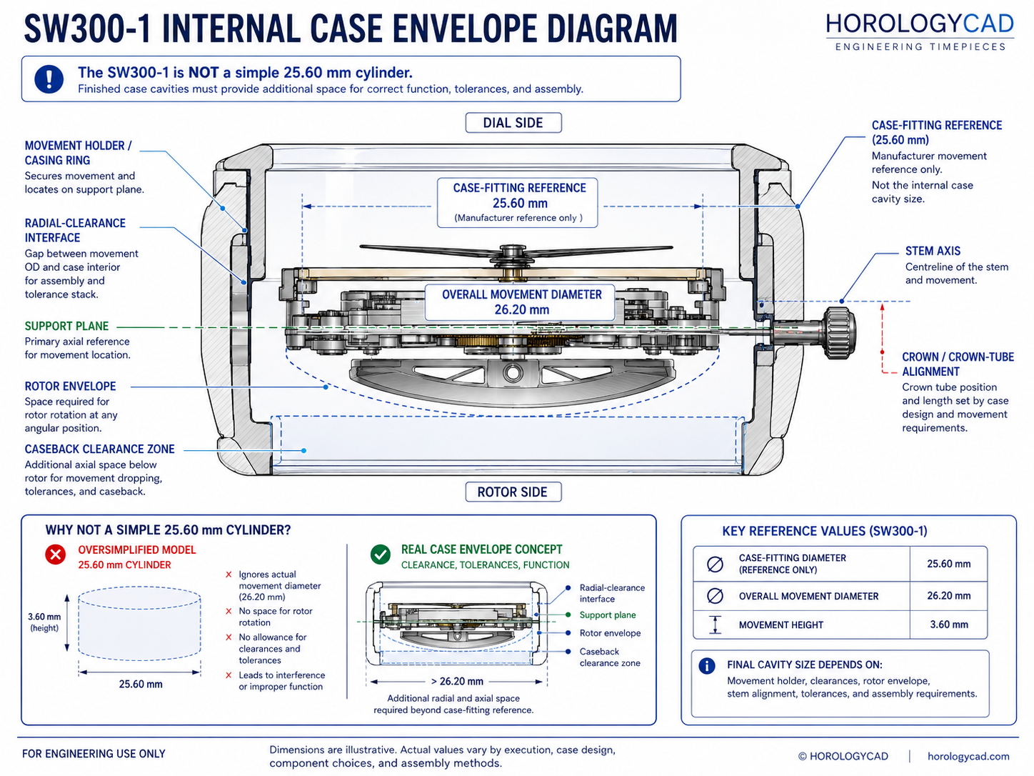
SW300-1 Casing Envelope
Sellita’s SW300-1 technical documentation identifies the movement as a three-dimensional casing system rather than a single simple cylinder.
The principal headline dimensions are:
- 25.60 mm case-fitting diameter
- 3.60 mm movement height
- 11½-ligne size class
These dimensions serve different functions.
The 25.60 mm dimension identifies the principal manufacturer casing-fit reference.
The 3.60 mm height describes the movement itself, not the finished watch stack.
The finished case cavity should therefore not be represented as one unsupported cylindrical diameter.
The designer must determine:
- which feature locates the movement
- which regions require clearance
- which surface establishes the support plane
- how the holder or clamps interact with the case
- how the movement enters and leaves the case
- how the dial and hands sit above the movement
- how the rotor is protected below the movement
- how the crown tube is aligned from the stem axis
The SW300-1’s thinness makes this more important, not less.
A slim movement leaves less room for careless packaging.
Related engineering reference: Internal Case Geometry & Movement Cavity Sizing
SW300-1 Internal Case Envelope Diagram
Movement Diameter and Internal Case Geometry
The 25.60 mm case-fitting dimension establishes a manufacturer casing reference.
It does not automatically establish the finished case-cavity diameter.
The internal case may also need to accommodate:
- movement holder
- casing ring
- locating shoulders
- casing clamps
- clamp screws
- radial assembly clearance
- coating or finishing buildup
- anti-rotation features
- inspection access
- service-tool access
A cavity modelled directly at the nominal movement dimension may become difficult or impossible to assemble after manufacturing variation is introduced.
It may also apply uncontrolled force to the movement or holder.
The designer must define:
- which component contacts the case
- which surface establishes concentricity
- which feature limits radial movement
- which feature prevents rotation
- how the movement enters the case
- how the movement is removed for service
The objective is not merely to make the movement fit.
The objective is to locate it predictably.
Related engineering reference: Internal Case Geometry & Movement Cavity Sizing
Radial Clearance and Movement Location
Radial clearance is the controlled allowance between the locating components of the movement system and the surrounding case structure.
The relevant interface may be:
- movement to case
- movement to holder
- holder to case
- casing ring to case
- clamp system to case
The correct allowance depends on:
- holder architecture
- component material
- machining method
- surface finish
- coating
- dimensional tolerance
- assembly method
- inspection strategy
- service requirements
Insufficient clearance can produce:
- difficult insertion
- forced seating
- movement or holder distortion
- stem-axis displacement
- dial displacement
- date-window displacement
- surface damage
- dependence on hand fitting
Excessive clearance can produce:
- radial movement
- rotation
- date-window displacement
- dial movement
- stem side loading
- inconsistent crown feel
- overdependence on clamps
There is no responsible universal cavity addition suitable for every SW300-1 case.
Clearance must be allocated to a defined interface within a defined architecture.
Related engineering reference: Radial Clearance
Anti-Rotation Control
Radial location and rotational control are separate functions.
A circular cavity may establish approximate concentricity while still permitting movement or holder rotation.
Rotation can affect:
- stem alignment
- crown function
- dial position
- date-window alignment
- hand alignment
- clamp loading
- assembly consistency
Anti-rotation may be provided through:
- movement-holder geometry
- casing clamps
- keyed features
- locating tabs
- dedicated case geometry
The setting stem must not be treated as a structural anti-rotation pin.
The stem is an operating component.
It is not a substitute for movement retention.
Movement Height and Finished Watch Thickness
The SW300-1 movement height is 3.60 mm.
That dimension represents only one part of the complete watch stack.
Finished thickness must also account for:
- movement seating
- dial support
- dial thickness
- hand-fitting height
- hand-to-hand clearance
- hand-to-crystal clearance
- rehaut depth
- crystal thickness
- crystal retention
- rotor clearance
- caseback internal depth
- caseback wall thickness
- caseback stiffness
- gasket compression
- movement retention
- manufacturing variation
- finishing variation
A case designed around the movement height alone will usually be incorrect.
Potential consequences include:
- rotor contact
- hand contact
- movement compression
- weak caseback construction
- excessive caseback depth
- greater finished thickness than expected
- incorrect crown-axis position
- compromised sealing geometry
A well-proportioned SW300-1 case is possible.
The complete axial stack must be resolved before the exterior thickness is fixed.
Related engineering reference: Movement Height vs Case Thickness
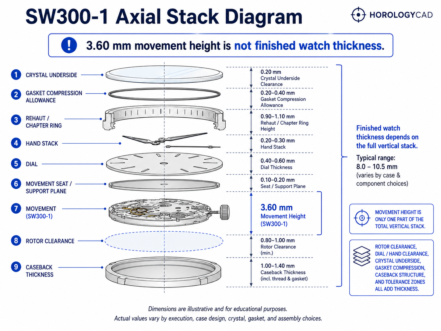
Axial Stack Control
The axial stack controls the vertical relationship between:
- caseback
- rotor
- movement
- movement seat
- dial
- hands
- rehaut
- crystal
The SW300-1 is often chosen because the designer wants a thinner finished watch.
That creates pressure to compress the stack.
The caseback side must provide free operating space for the automatic winding system.
The dial side must provide controlled support and clearance for the dial and hands.
Insufficient axial space can cause:
- rotor rubbing
- hand contact
- dial loading
- movement compression
- caseback interference
- reduced winding efficiency
Excessive uncontrolled space can cause:
- movement lift
- dial movement
- stem misalignment
- retention inconsistency
- impact noise
- variable crown operation
Axial clearance is not arbitrary empty space.
It is a controlled relationship between real surfaces and their tolerance limits.
Related engineering reference: Axial Clearance
SW300-1 Axial Stack Diagram
Rotor Clearance and Caseback Architecture
The rotor occupies a moving envelope behind the movement.
The caseback cannot be developed only from the desired exterior profile.
Its internal geometry must preserve rotor clearance through:
- movement seating variation
- rotor motion
- rotor endshake
- manufacturing tolerance
- caseback deflection
- gasket compression
- finishing buildup
- shock loading
Insufficient clearance can cause:
- rubbing
- scraping noise
- winding drag
- reduced winding efficiency
- witness marks
- wear debris
- movement damage
A common SW300-1 mistake is to assume that the reduced movement height removes rotor risk.
It does not.
The rotor still requires protected space.
A thin movement can still be paired with a poorly designed caseback.
The rotor space should be resolved before the external caseback profile is finalised.
The caseback must then satisfy several requirements simultaneously:
- rotor protection
- structural stiffness
- gasket support
- thread or retention geometry
- service access
- acceptable external proportion
Related engineering reference: Rotor Clearance Requirements
Caseback Stiffness in a Slim Watch
The SW300-1 allows the designer to reduce internal stack height.
That should not be interpreted as permission to reduce the caseback to an inadequately supported shell.
A thin caseback must still resist:
- external pressure
- assembly load
- gasket compression
- thread loading
- local deformation
- impact
- bending toward the rotor
Caseback stiffness depends on:
- material
- wall thickness
- internal span
- exterior curvature
- thread geometry
- gasket position
- machining features
- display-back construction where applicable
A caseback that deflects can reduce rotor clearance even when the nominal CAD gap appears sufficient.
The rotor envelope must therefore be protected under realistic structural conditions, not only in the undeformed model.
This is one of the defining SW300-1 case-design problems:
the movement allows thinness, but the caseback must still behave like an engineered structure.
Winding and Functional Test Information
The SW300-1 supports automatic and manual winding.
Sellita technical documentation provides controlled winding and test information for workshop and production use.
These instructions relate to:
- manual winding through the stem
- testing with the automatic winding system installed
- testing without the automatic system installed
- testing with the self-winding system
These are servicing and controlled-test procedures rather than everyday user instructions.
For the case designer, the important implications are:
- the crown and stem system must permit smooth manual winding
- the setting stem must remain aligned throughout operation
- the crown must provide suitable access
- the keyless works must not receive lateral load
- the rotor must remain free to operate
- the caseback must not introduce automatic-winding interference
A case can satisfy nominal movement dimensions and still compromise winding performance through poor stem alignment or insufficient rotor clearance.
Stem Axis and Crown-Tube Alignment
The crown position must be derived from the movement stem axis.
It should not be selected visually and joined to the movement afterward.
The stem axis controls:
- case-wall bore position
- crown-tube centreline
- crown seating
- winding feel
- setting feel
- date correction where applicable
- keyless-works loading
- crown-gasket alignment
- crown-guard geometry
- case-wall material around the tube
The reduced vertical architecture of an SW300-1 case makes stem-height errors especially visible.
There is less unused internal volume available to hide a poorly placed crown axis.
If the crown tube is misplaced, the stem may be forced into alignment during assembly.
The watch may still operate, but the system can suffer from:
- stem bending
- rough winding
- poor setting feel
- keyless-works side load
- uneven gasket compression
- crown-tube wear
- premature failure
- visibly incorrect crown position
The movement support plane, stem axis, case-wall bore, crown tube, and crown should be developed as one mechanical chain.
The crown is both:
- a user interface
- a sealing interface
Related engineering reference: Crown and Stem Alignment in Watch Cases
Stem Height and Crown-Tube Position
Stem height is one of the most important movement-led case dimensions.
For the SW300-1, the stem axis must be interpreted from the relevant technical drawing convention and transferred into the case datum system correctly.
The designer must define:
- movement support plane
- movement seating level
- stem centreline
- case-tube bore height
- crown-tube shoulder
- crown seat
- gasket relationship
- external crown centreline
- remaining structural material around the tube
Small stem-height errors can cause large practical problems.
The watch may still assemble, but:
- crown operation may feel rough
- the stem may drag
- the keyless works may receive side load
- the crown gasket may compress unevenly
- the crown may sit visibly high or low
A correct SW300-1 case uses the stem axis as a datum.
The exterior crown position is designed around that datum.
Related engineering reference: Stem Height to Crown Tube Position Relationship
Date, No-Date, and Dial Interface
The SW300-1 may be encountered in date or no-date executions depending on the selected movement and supplier configuration.
The exact execution matters.
A date-equipped SW300-1 requires coordination of:
- date-wheel location
- dial aperture
- date correction
- rotational movement position
- rehaut opening
- chapter-ring position
- crown settings
A no-date execution removes the date display and related dial aperture.
It does not remove the need for:
- exact movement identification
- correct stem interpretation
- rotor clearance
- movement retention
- dial-side stack validation
- casing verification
The dial side must be coordinated with:
- movement location
- dial seat
- case opening
- date aperture where applicable
- rehaut
- chapter ring
- crystal
- hand stack
Important dial constraints include:
- dial-seat diameter
- support geometry
- dial thickness
- dial-fixing arrangement
- date-window position
- movement rotational position
- rehaut depth
- chapter-ring clearance
- hand-stack height
- crystal underside clearance
- visual centring
The dial is not merely a decorative disc above the movement.
It is part of the axial stack and the visible movement-location system.
If the movement shifts radially or rotationally, a date display may misalign.
If the dial seat is incorrect, the dial may sit too high, too low, or without adequate support.
The dial-side architecture should be resolved before final case thickness and crystal position are declared.
Related engineering reference: Dial Integration & Case Interface
Dial Attachment
The Sellita documentation identifies manufacturer dial-fastener references within the movement system.
The final dial programme must confirm:
- attachment method
- locking geometry
- engagement
- dial thickness
- date-disc clearance where applicable
- service release method
The case should not compensate for an incorrectly specified dial.
Movement, dial, and case should be developed as one coordinated assembly.
Changes to dial thickness, attachment position, applied markers, dial construction, or surface build-up may alter the axial stack or assembly process.
Hand-Fitting Heights and Crystal Clearance
The selected hand-fitting execution changes the dial-side stack.
The SW300-1 case must provide clearance for:
- hour hand above the dial
- minute hand above the hour hand
- seconds hand above the minute hand
- seconds hand below the crystal
- hand-fitting variation
- dial-thickness variation
- hand flex
- shock displacement
- crystal-position variation
- manufacturing tolerance
A case can have correct movement diameter, radial location, rotor clearance, and crown alignment and still fail at the hand stack.
Possible failures include:
- hour hand contacting the dial
- minute hand contacting the hour hand
- seconds hand contacting the minute hand
- seconds hand contacting the crystal
- hand tips contacting the rehaut
- inadequate shock allowance
The highest operating hand should be treated as a dynamic upper boundary.
The crystal underside must remain clear under expected tolerance and operating conditions.
This is particularly important in a slim watch because dial-side clearance may be reduced aggressively.
Related engineering references: Hand Stack Height and Clearance Requirements and Dial to Crystal Clearance
Detailed Hand-Height Data
The complete manufacturer hand-height and dial-side data should be made available through:
- an expandable technical-reference section
- a separate HorologyCAD reference table
- direct consultation of the official Sellita document
The main article should identify the need to confirm the exact hand-fitting execution without overwhelming the introductory specification layer.
Movement Holder and Retention Strategy
The SW300-1 must be retained securely without being:
- distorted
- pinched
- allowed to shift
- allowed to rotate
- compressed by the caseback
A complete retention system should control:
- radial movement
- axial movement
- rotation
- dial alignment
- stem loading
- shock response
- service removal
Possible strategies include:
- manufacturer-style casing clamps
- dedicated movement holder
- casing ring
- spacer ring
- locating shoulders
- combined locating and retention geometry
The correct method depends on:
- case material
- machining method
- production quantity
- assembly order
- water-resistance target
- dial architecture
- service strategy
The movement should not be trapped accidentally between the dial side and caseback.
The caseback should not become the sole retention feature unless the full axial stack has deliberately been engineered for that role.
Retention must be controlled.
It should not depend on unknown compression.
Related engineering reference: Movement Securing Methods
Setting-Stem Removal and Service Access
A professional SW300-1 case must allow the movement to be installed, tested, removed, and recased without damage.
Service access should be considered during CAD development, not after the first prototype has already been machined.
The case architecture should provide:
- visible access to required release points
- sufficient tool approach
- adequate clearance around the movement
- stable support during stem removal
- access to clamps or holder features
- a service sequence that avoids levering against finished surfaces
The release point and retention features should not be hidden behind:
- an inaccessible holder
- a case-wall obstruction
- a casing clamp
- a decorative internal feature
- an assembly sequence that traps the movement
A case may hold the movement securely and still be poorly engineered if the movement cannot be removed safely.
Service access must be reviewed during CAD development.
Sealing and Water-Resistance Architecture
Water resistance must be integrated into the movement-led case architecture from the beginning.
The case must coordinate:
- crown sealing
- crown-tube alignment
- caseback sealing
- crystal sealing
- gasket compression
- thread engagement
- sealing-surface finish
- structural stiffness
- axial-stack behaviour
- service replacement
Thin-case architecture can reduce the material available around:
- crown-tube supports
- gasket grooves
- crystal seats
- caseback threads
- retaining shoulders
- sealing surfaces
The designer must avoid sacrificing:
- caseback stiffness
- crown-tube support
- crystal-seat rigidity
- gasket-groove integrity
- thread depth
- sealing-surface width
- internal shoulder strength
A misaligned crown tube can compromise crown feel and gasket function simultaneously.
A shallow caseback can compromise rotor clearance or gasket behaviour if the internal architecture has not been resolved.
Water resistance is not added after movement fit is complete.
It is part of the same engineering system.
Related engineering references: Water Resistance Engineering in Watch Cases and Caseback Sealing System
Case Rigidity and Thinness
The SW300-1 makes thinner case architecture possible.
It does not remove structural requirements.
A thin case must still preserve adequate rigidity around:
- mid-case walls
- crown-tube bore
- crystal seat
- bezel interface
- caseback thread
- gasket grooves
- movement-locating shoulders
- lug junctions
Reducing material without considering load paths can produce:
- case distortion
- sealing-surface movement
- thread weakness
- crown-tube instability
- crystal-seat deformation
- reduced impact resistance
- rotor-clearance loss under deflection
The correct objective is not the smallest possible dimension at every point.
The objective is an efficient structure in which material is retained where it performs a mechanical function.
Slimness should result from controlled packaging, not structural neglect.
Manufacturing and Tolerance Strategy
A CAD model can appear correct while remaining difficult or impossible to manufacture consistently.
The case architecture must account for:
- tool access
- cutter radius
- bore accuracy
- concentricity
- flatness
- perpendicularity
- thread geometry
- finishing removal
- coating buildup
- inspection method
- component variation
- assembly variation
Every critical interface should have:
- nominal dimension
- tolerance
- functional purpose
- inspection method
The designer should be able to explain:
- what locates the movement
- what retains it
- what prevents rotation
- what controls the stem axis
- what protects the rotor
- what supports the dial
- what establishes hand clearance
- what compresses each gasket
- how each relationship will be inspected
If a critical feature cannot be measured or inspected, its production control is weak.
A slim case has less unused volume available to absorb uncontrolled variation.
Large safety allowances added late in the design process can remove the thickness advantage of the SW300-1.
The objective is not to eliminate all clearance.
The objective is to allocate clearance and tolerance deliberately where mechanically required.
Related engineering references: Watch Case Tolerances and CNC Machining Constraints in Watch Cases
Manufacturing Suitability
The SW300-1 is highly suitable for refined slim automatic watch production when the case is engineered correctly.
| Use case | Suitability | Reason |
|---|---|---|
| CNC prototyping | Good to excellent | Slim architecture requires disciplined stack control |
| Low-volume production | Good to excellent | Strong modern Swiss movement option where sourcing is controlled |
| Independent brands | Excellent | Supports premium Swiss positioning and refined proportions |
| First serious mechanical project | Moderate | Less forgiving than larger or thicker entry-level movements |
| Slim automatic watches | Excellent | 3.60 mm height supports lower-profile architecture |
| Premium dress watches | Excellent | Slim Swiss movement suits restrained proportions |
| Refined sports watches | Excellent | Strong balance of thinness and automatic functionality |
| Lower-profile dive watches | Good to excellent | Suitable where rotor clearance and sealing are controlled |
| Haute horology context | Moderate | Strong base calibre, but finishing, modification, and broader product context matter |
The SW300-1 is technically capable and packaging-efficient, but it is not casual to integrate.
It rewards disciplined engineering and exposes poor tolerance control, especially around:
- axial stack
- rotor clearance
- caseback stiffness
- crown alignment
- hand clearance
- sealing geometry
- movement retention
Service Ecosystem and Long-Term Use
The SW300-1 benefits from Sellita production relevance and a familiar Swiss automatic servicing context.
It is suitable for watches intended to be:
- maintained
- regulated
- repaired
- recased
- retained long term
Serviceability also imposes case-design requirements.
A well-resolved case should permit:
- controlled stem removal
- access to retention features
- holder or clamp removal
- non-destructive movement extraction
- caseback servicing
- gasket replacement
- reliable recasing
- functional checks after assembly
A case that cannot be serviced cleanly is not fully engineered.
Thinness should never depend on making routine service access difficult or destructive.
Collector and Product Perception
Collectors generally understand the SW300-1 as a slim Swiss automatic movement with a stronger technical position than standard workhorse calibres where case thickness matters.
It is recognised for:
- reduced movement height
- premium case potential
- modern Sellita production
- Swiss movement positioning
- relationship to ETA 2892-A2-style architecture
- suitability for refined automatic watches
That perception can be strengthened or weakened by the finished watch.
In a poorly designed case, the movement’s thinness may be wasted by:
- excessive caseback depth
- a tall rehaut
- thick crystal architecture
- poor crown alignment
- weak finishing
- poor movement integration
In a well-engineered watch, the SW300-1 can feel like the correct movement for the design:
- slim
- refined
- technically appropriate
- maintainable
- professionally integrated
The movement provides a slim Swiss foundation.
The case determines whether that foundation feels properly used.
Known Weaknesses and Trade-Offs
The SW300-1 is a strong movement, but it is not ideal for every project.
Its trade-offs include:
- higher cost than common entry-level movements
- greater sourcing complexity than broadly available Japanese calibres
- premium expectations placed on the finished watch
- reduced tolerance margin in aggressively thin cases
- continued need for rotor clearance
- execution-specific date and power-reserve considerations
- limited benefit where the surrounding case remains thick
- structural risks if thinness is pursued without adequate material
These characteristics do not make the SW300-1 a poor movement.
They define where the surrounding watch must work harder.
A successful SW300-1 watch should rely on:
- controlled slim-case architecture
- disciplined movement integration
- good crown feel
- strong structural design
- appropriate dial and crystal proportions
- finishing quality
- serviceability
- coherent engineering
It should not rely on the movement name alone.
Relationship to the ETA 2892-A2
The Sellita SW300-1 is commonly positioned in the same broad slim Swiss automatic category as the ETA 2892-A2.
The comparison is useful because both movements share:
- a similar 11½-ligne movement class
- slim automatic architecture
- central rotor winding
- three-hand display
- premium case-thickness potential
From a case-design perspective, both require careful control of:
- slim axial-stack height
- automatic rotor clearance
- caseback depth
- crown and stem alignment
- movement securing
- dial-side stack planning
- thin-case rigidity
- sealing geometry
- manufacturing tolerance
This does not mean they should be treated as automatically identical.
The final case must always be checked against:
- the exact movement
- the exact technical drawing
- hand-height execution
- dial system
- date configuration
- holder arrangement
- current manufacturer data
Similar dimensions do not guarantee complete casing interchangeability.
SW300-1 Ecosystem and Related Movements
The SW300-1 should be understood within a broader movement ecosystem that may include:
- ETA 2892-A2 — a historically important slim Swiss automatic reference point
- Sellita SW300-1 — the calibre covered by this page
- Sellita SW330 family — related GMT architecture requiring separate validation
- Sellita SW360 family — related small-seconds architecture requiring separate validation
- Sellita SW200-1 — standard-height Sellita automatic architecture
- ETA 2824-2 — standard-height Swiss automatic architecture
Similar naming, similar function, or similar nominal diameter does not prove casing compatibility.
The word “compatible” should never replace dimensional verification.
What the SW300-1 Does Not Decide
The movement does not define:
- final case diameter
- bezel design
- lug geometry
- case-wall thickness
- crown shape
- crown-tube installation
- caseback profile
- gasket selection
- crystal system
- rehaut depth
- dial opening
- finishing specification
- machining strategy
- external proportion
A slim movement reduces one category of packaging difficulty.
It does not replace case engineering.
The movement establishes the internal reference.
The designer must convert that reference into:
- controlled geometry
- tolerance behaviour
- assembly logic
- inspection criteria
- prototype validation
- repeatable production architecture
Common SW300-1 Case-Design Mistakes
Assuming 3.60 mm movement height automatically creates a thin watch
Movement height excludes dial, hands, crystal, rotor clearance, caseback, sealing, and structural material.
Treating 25.60 mm as the finished cavity diameter
The case-fitting diameter is a manufacturer reference, not a complete finished case cavity.
Reducing caseback depth without checking the rotor
The automatic rotor still requires protected operating clearance.
Reducing caseback thickness without checking stiffness
A thin caseback can deflect toward the rotor even when nominal CAD clearance looks sufficient.
Positioning the crown visually
The crown tube must be positioned from the movement stem axis.
Forcing the stem into alignment
A watch can operate while the stem and keyless works are already being side-loaded.
Ignoring date-window position where applicable
Small radial or rotational errors can create obvious date-window displacement.
Treating the dial as independent from movement position
The dial is part of the visible movement-location system.
Failing to validate hand-to-crystal clearance
A slim dial-side stack can fail even if the movement fits perfectly.
Reducing crystal clearance too aggressively
The highest operating hand needs tolerance and shock allowance.
Using the caseback to crush or trap the movement
Retention should be deliberate and repeatable.
Assuming SW300-1 and ETA 2892-A2 cases are automatically interchangeable
Similar architecture does not prove complete casing compatibility.
Ignoring machining and finishing allowance
A correct nominal CAD model may become wrong after real manufacturing variation.
Adding gasket geometry after the case has been designed
Sealing affects wall thickness, axial stack, threads, and crown alignment.
Using late-stage safety margins that destroy the thin-case advantage
Slimness must be engineered from the beginning, not recovered at the end.
Designing without an assembly sequence
A component can fit in CAD but remain impossible to install or service.
Treating one successful prototype as production proof
A working prototype demonstrates possibility.
Production requires repeatability.
CAD Difficulty Assessment
The SW300-1 can appear simple in CAD because its headline dimensions are compact and familiar.
That impression is misleading.
A basic visual representation is relatively straightforward.
A professional, manufacturable, serviceable, and tolerance-aware SW300-1 case is considerably more demanding.
| Task | Approximate difficulty |
|---|---|
| Basic conceptual movement placement | 3/10 |
| Controlled slim automatic case layout | 6/10 |
| Professional movement-fit case architecture | 8/10 |
The main difficulty lies in:
- radial tolerance
- movement location
- crown feel
- stem alignment
- rotor clearance
- caseback depth
- caseback stiffness
- dial-side stack control
- sealing geometry
- structural wall control
- repeatable assembly
- service access
A beginner can place the SW300-1 inside a circular cavity.
A professional case design defines how the movement is located, protected, sealed, retained, and serviced while preserving the advantage of its reduced height.
Physical-Sample Validation
Manufacturer documentation establishes the nominal technical basis.
Physical inspection confirms the actual components entering the project.
Before final CAD release, compare the documentation with:
- physical SW300-1 movement
- selected dial
- intended hand set
- setting stem
- crown
- crown tube
- casing clamps
- movement holder
- prototype components
Where practical, inspect:
- movement envelope
- case-fitting region
- movement height
- stem-axis relationship
- setting-stem positions
- rotor envelope
- dial interface
- clamp geometry
- hand-height execution
Physical measurements should not casually override official drawings.
Measurement uncertainty, access limitations, and component condition must be considered.
Where the drawing, supplier information, and physical component appear to disagree:
- stop the design release
- identify the discrepancy
- verify document revision
- confirm movement execution
- consult the supplier or manufacturer where necessary
- record the resolution
An unresolved discrepancy should not be hidden inside an arbitrary clearance.
SW300-1 Pre-Prototype Verification Checklist
Before releasing the case for prototyping, confirm that:
- physical calibre is identified as SW300-1
- exact execution is recorded
- technical-document revision is recorded
- applicable 25.60 mm casing fit is identified
- 3.60 mm movement height is understood as movement height only
- date or no-date arrangement is confirmed
- hand-fitting-height execution is confirmed
- dial specification is confirmed
- dial attachment is confirmed
- date aperture is coordinated where applicable
- setting-stem option is confirmed
- crown system is confirmed
- locating datum is defined
- radial locating interface is defined
- holder or casing-ring system is defined
- clamp type and screw are defined where applicable
- stem-release access is preserved
- anti-rotation control is defined
- radial tolerances are assigned
- axial tolerances are assigned
- rotor clearance is protected
- caseback clearance is checked at worst case
- caseback stiffness is reviewed
- stem axis is transferred into the case datum system
- crown-tube alignment is verified
- crown positions are verified
- dial-seat height is controlled
- hand-to-hand clearance is protected
- hand-to-dial clearance is protected
- hand-to-marker clearance is protected
- hand-to-rehaut clearance is protected
- hand-to-crystal clearance is protected
- movement lift is controlled
- movement rotation is controlled
- gasket compression does not compromise movement clearance
- machining allowances are included
- finishing allowances are included
- inspection methods exist
- assembly order has been reviewed
- service removal is possible
- physical-sample inspection is recorded
- representative production components will be used in the prototype
This checklist does not replace production drawings or prototype testing.
It controls the principal SW300-1 movement-to-case risks before manufacture begins.
Movement-Led SW300-1 Case-Design Workflow
- Confirm the movement.
Identify the exact calibre, execution, date or no-date arrangement, grade, hand height, and supplied components.
- Secure the official documentation.
Record the document title, revision, date, and source.
- Create the project movement record.
Record the physical marking, supplier, dial, hands, stem, holder, clamps, and crown system.
- Extract manufacturer geometry.
Review the 25.60 mm case-fitting reference, 3.60 mm movement height, dial interface, setting-stem information, automatic-winding architecture, and casing references.
- Inspect the physical components.
Compare the actual movement and selected parts against the documented specification.
- Select the locating architecture.
Define which component establishes position.
- Resolve radial fit.
Allocate clearance and tolerance at the selected locating interface.
- Resolve anti-rotation.
Provide rotational control independent of the setting stem.
- Resolve the axial stack.
Build the complete stack from caseback to crystal.
- Protect the rotor.
Resolve internal caseback geometry before fixing the exterior profile.
- Review caseback stiffness.
Confirm that the caseback remains structurally adequate and does not deflect into the rotor envelope.
- Transfer the stem axis.
Position the case-wall bore and crown tube from the movement datum system.
- Resolve the crown system.
Establish stem length, operating positions, tube projection, crown seating, and gasket behaviour.
- Resolve dial and hands.
Coordinate dial seat, date aperture where applicable, selected hand height, rehaut, and crystal.
- Define retention.
Control radial movement, axial lift, and rotation without distorting the movement.
- Preserve service access.
Ensure that stem release, holder, clamps, and removal sequence remain practical.
- Integrate sealing.
Coordinate crown, crystal, and caseback sealing with the existing architecture.
- Apply tolerances.
Assign tolerances and inspection methods to all critical interfaces.
- Validate assembly and service.
Confirm that the watch can be assembled, opened, and serviced without damage.
- Build and inspect the prototype.
Use representative components and record deviations from CAD.
This sequence prevents the common mistake of selecting a thin movement, drawing an attractive low-profile exterior, and only later discovering that rotor clearance, hand clearance, crown alignment, structural stiffness, or sealing geometry has been compromised.
Related engineering reference: Movement to Case Fit
Prototype Validation
The first prototype is an engineering test article.
After assembly, verify that:
- movement enters without forced seating
- holder or casing ring remains undistorted
- casing clamps seat correctly where used
- clamp screws remain accessible where used
- stem-release access remains accessible
- movement cannot shift radially
- movement cannot rotate
- movement cannot lift axially
- stem enters without lateral deflection
- winding is smooth
- time setting is smooth
- date correction operates correctly where applicable
- crown positions are distinct
- dial remains centred
- date aperture remains aligned where applicable
- hands clear one another
- hands clear the dial
- hands clear applied markers
- hands clear the rehaut
- hands clear the crystal
- rotor rotates freely
- no caseback witness marks appear
- no abnormal rotor noise is present
- caseback sealing does not reduce rotor clearance
- caseback stiffness is acceptable
- crown and crystal sealing function as intended
- case can be reopened
- movement can be removed
- movement can be recased repeatably
Where appropriate, repeat checks:
- dial up
- dial down
- crown up
- crown down
- before final caseback tightening
- after final assembly
- after sealing tests
- after reopening and recasing
Prototype Measurement Record
For each prototype, record:
- prototype revision
- CAD revision
- technical-document revision
- movement identification
- movement grade
- date or no-date execution
- dial identification
- hand-set identification
- hand-height execution
- crown and tube identification
- stem option
- holder or clamp revision
- radial-interface measurement
- movement seating position
- caseback clearance
- caseback stiffness observation
- dial position
- date-window alignment where applicable
- hand clearances where practical
- winding observations
- setting observations
- sealing-test result
- failed checks
- corrective action
- final disposition
Possible dispositions include:
- accepted
- accepted with controlled deviation
- rework required
- redesign required
- rejected
A prototype should not be accepted merely because it can be assembled.
Acceptance requires correct location, free operation, serviceability, structural adequacy, and conformity with the intended engineering requirements.
Production Acceptance Criteria
Before approving the architecture for production, confirm that:
- critical dimensions have tolerances
- tolerances reflect the manufacturing process
- inspection methods exist
- worst-case conditions have been reviewed
- movement installation is repeatable
- movement retention is repeatable
- stem access is repeatable
- crown function is repeatable
- rotor clearance is repeatable
- caseback stiffness is repeatable
- dial and date alignment are repeatable where applicable
- hand clearance is repeatable
- sealing is repeatable
- disassembly and recasing are repeatable
- approved deviations are documented
- production samples match the approved prototype
One successful prototype proves possibility.
Production approval requires repeatability.
Related HorologyCAD Engineering Pages
Continue through the movement-led case-design system.
Start With Movement Fit
Define Clearance and Case Architecture
Resolve Crown, Stem, Dial, and Hands
- Crown and Stem Alignment in Watch Cases
- Stem Height to Crown Tube Position Relationship
- Dial Integration & Case Interface
- Hand Stack Height and Clearance Requirements
- Dial to Crystal Clearance
Control Retention, Sealing, and Manufacturing
- Movement Securing Methods
- Water Resistance Engineering in Watch Cases
- Caseback Sealing System
- Watch Case Tolerances
- CNC Machining Constraints in Watch Cases
Continue the SW300-1 Cluster
- Sellita SW300-1 Case Design Constraints
- Sellita SW300-1 Case Design Guide
- Sellita SW300-1 Case Core: Movement-Fit CAD System
Compare With Related Movements
- Sellita SW200-1 Dimensions & Technical Data
- ETA 2892-A2 Dimensions & Technical Data
- ETA 2824-2 Dimensions & Technical Data
- Miyota 9015 Dimensions & Technical Data
- Seiko NH35 / NH36 Dimensions & Technical Data
HorologyCAD Design Position
The Sellita SW300-1 is not merely a slim movement specification.
It is a fixed internal engineering system around which the watch case must be developed.
Its case-fitting diameter, movement height, stem axis, dial interface, date or no-date execution, hand-fitting execution, rotor, and retention requirements all influence the finished watch.
When those relationships are interpreted correctly, the designer can create a case that:
- assembles predictably
- locates the movement accurately
- controls rotation
- protects the automatic system
- aligns the crown and stem
- preserves dial and hand clearance
- uses the reduced movement height intelligently
- supports water resistance
- maintains structural stiffness
- controls manufacturing variation
- can be inspected
- remains serviceable
The principle is straightforward:
Begin with verified manufacturer data, establish the internal case architecture, preserve the slim movement advantage through controlled stack design, validate using real components, and develop the exterior around a mechanically resolved system.
Thinness must be engineered.
It cannot be assumed.
Next Step
For the complete movement-to-case relationship:
For movement-cavity sizing and location logic:
→ Internal Case Geometry & Movement Cavity Sizing
For SW300-1-specific failure boundaries:
→ Sellita SW300-1 Case Design Constraints
For the applied SW300-1 design process:
→ Sellita SW300-1 Case Design Guide
Return to HorologyCAD
HorologyCAD is a movement-led watch case design system for developing case architecture around real mechanical movements, manufacturable constraints, and functional assembly requirements.
→ Movement-Led Watch Case Design & Engineering
Technical Note
This page is based on identified Sellita SW300 / SW300-1 technical documentation and current SW300-1 reference checks.
Last checked against identified manufacturer documentation: 22 June 2026.
Manufacturer data should always be checked against the current official Sellita documentation and the exact movement execution used in the project.
HorologyCAD engineering guidance on case geometry, clearance, retention, stem alignment, sealing, assembly, slim-case architecture, caseback stiffness, and validation is interpretive design guidance. Final case architecture should be confirmed against physical components, prototype assembly, and production inspection.